Methods and systems for detecting defects in a reticle design pattern

a technology of reticle and design pattern, which is applied in the direction of photomechanical equipment, instruments, originals for photomechanical treatment, etc., can solve the problems of affecting yield, affecting yield, and more difficult reticles and consequently more expensive to manufactur

Active Publication Date: 2012-07-03
KLA CORP
View PDF405 Cites 93 Cited by
  • Summary
  • Abstract
  • Description
  • Claims
  • Application Information

AI Technical Summary

Problems solved by technology

Although they are implemented in semiconductor device designs to facilitate low k1 lithography, these RET make reticles more difficult and consequently more expensive to manufacture.
Marginal RET designs not noted by simulation checks translate into electrical failures in wafer fabrication, affect yield, and possibly remain unnoticed until wafer fabrication is complete.
Traditional methods employed in the inspection of complex mask patterns place tremendous demand on reticle inspection tools.
Performing an inspection of a conventional focus exposure matrix introduces a complication in that every exposure field is different.
Moreover, current reticle inspection techniques cannot detect the presence of an error in the design database.

Method used


Image

  • Methods and systems for detecting defects in a reticle design pattern
  • Methods and systems for detecting defects in a reticle design pattern
  • Methods and systems for detecting defects in a reticle design pattern

Examples


Embodiment Construction

[0050]As used herein, the term “reticle” is used interchangeably with the term “mask.” In addition, the term “defect” is used interchangeably with the term “anomaly.”

[0051]Turning now to the drawings, it is noted that the figures are not drawn to scale. In particular, the scale of some of the elements of the figures is greatly exaggerated to emphasize characteristics of the elements. It is also noted that the figures are not drawn to the same scale. Elements shown in more than one figure that may be similarly configured have been indicated using the same reference numerals.

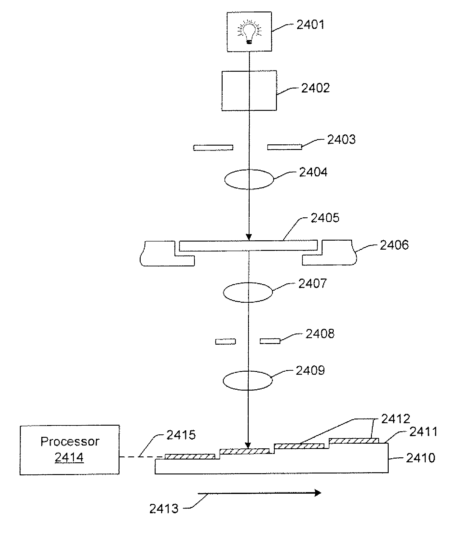
[0052]Methods described herein may implement modulation of focus of light illuminating reticles, each of which is used to expose by a step and repeat or a step and scan process a top layer of photoresist covering a test wafer. The reticles are printed on optimized film stacks, the type of optimization depending on the type of process level, which includes contact or via, gate, and trench. The base film stack is pr...


PUM

PropertyMeasurementUnit
heightsaaaaaaaaaa
wavelengthsaaaaaaaaaa

Abstract

Computer-implemented methods and systems for detecting defects in a reticle design pattern are provided. One computer-implemented method includes acquiring images of the reticle design pattern using a sensor disposed on a substrate arranged proximate to an image plane of an exposure system configured to perform a wafer printing process using the reticle design pattern. The images illustrate how the reticle design pattern will be projected on a wafer by the exposure system at different values of one or more parameters of the wafer printing process. The method also includes detecting defects in the reticle design pattern based on a comparison of two or more of the images corresponding to two or more of the different values.

Description

PRIORITY CLAIM[0001]This application claims priority to U.S. Provisional Application No. 60 / 916,915 entitled “Methods and Systems for Detecting Defects in a Reticle Design Pattern,” filed May 9, 2007, which is incorporated by reference as if fully set forth herein.BACKGROUND OF THE INVENTION[0002]1. Field of the Invention[0003]This invention relates to methods and systems for detecting defects in a reticle design pattern. Certain embodiments relate to methods that include acquiring images of a reticle design pattern using a sensor disposed on a substrate arranged proximate to an image plane of an exposure system configured to perform a wafer printing process using the reticle design pattern.[0004]2. Description of the Related Art[0005]The following descriptions and examples are not admitted to be prior art by virtue of their inclusion within this section.[0006]The rapid decrease in k1 (line-width=k1(λ / NA)) in lithographic manufacture of semiconductor devices has necessitated the use...

Claims


Application Information

Patent Timeline
Patent Type & Authority Patents(United States)
IPC IPC(8): G06K9/00G01N21/00
CPCG03F1/84G03F7/7065G03F7/70666G03F7/7085
Inventor PETERSON, INGRID B.YUM, ED
Owner KLA CORP
Why Eureka
Try Eureka