Mobile communications system and method for providing common channel coverage using beamforming antennas

a beamforming antenna and mobile communication technology, applied in the field of mobile communication systems, can solve the problems of increasing interference and ineffective solution in limited wireless radio access systems

Active Publication Date: 2012-07-03
INTERDIGITAL TECH CORP
View PDF42 Cites 10 Cited by
  • Summary
  • Abstract
  • Description
  • Claims
  • Application Information

AI Technical Summary

Benefits of technology

[0028]The implementing radio network can have a controlling interface connected to the base stations. In such case, the information related to the detected sounding pulse can be communicated to the interface by each base station detecting the sounding pulse. One or more of the base stations that detected the sounding pulse can then be chosen based on the communicated information so that only the chosen base stations direct a communication beam to the mobile unit. In this way the radio access network can selectively limit the selection made by the mobile unit.

Problems solved by technology

In such systems, a beacon signal radiated by each base station is an omnidirectional high powered transmission that has a tendency to generate interference.
This complication results in wireless radio access systems that transmit common channels using conventional omni-directional antennas that cover entire cells or cell sectors.
However, an increase in transmission power by all radio access points, for example, base stations, also results in an increase in interference.
Such a solution is ineffective in wireless radio access systems that are limited by interference.

Method used


Image

  • Mobile communications system and method for providing common channel coverage using beamforming antennas
  • Mobile communications system and method for providing common channel coverage using beamforming antennas
  • Mobile communications system and method for providing common channel coverage using beamforming antennas

Examples


Embodiment Construction

[0038]The present invention is described with reference to the drawing figures wherein like numerals represent like elements throughout. The present invention can be applied to some or all of a systems' downlink common channels. For reason of simplicity, the invention as applied to a UMTS system for downlink common channels is described herein. However, the proposed invention is applicable in any wireless system.

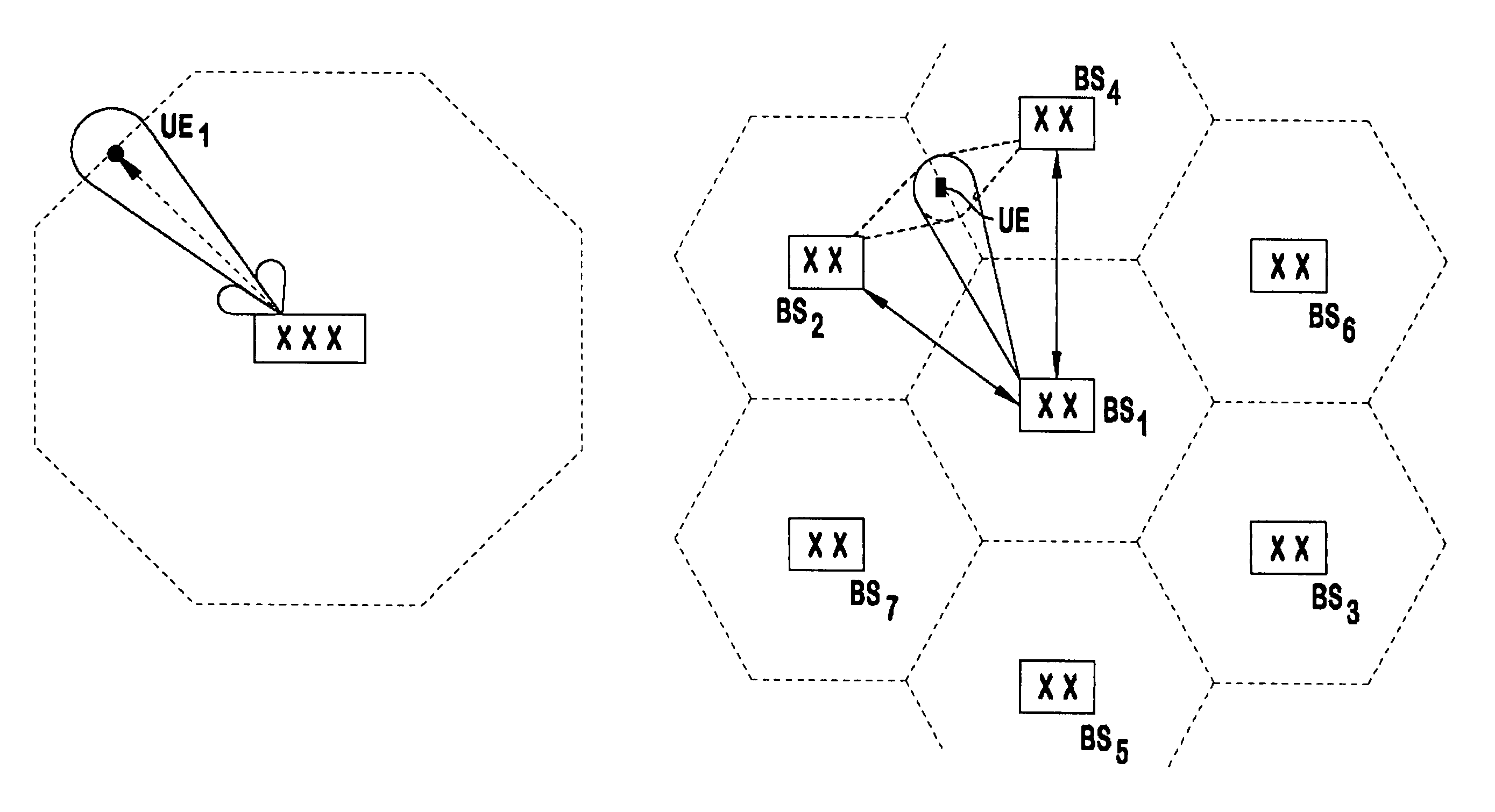
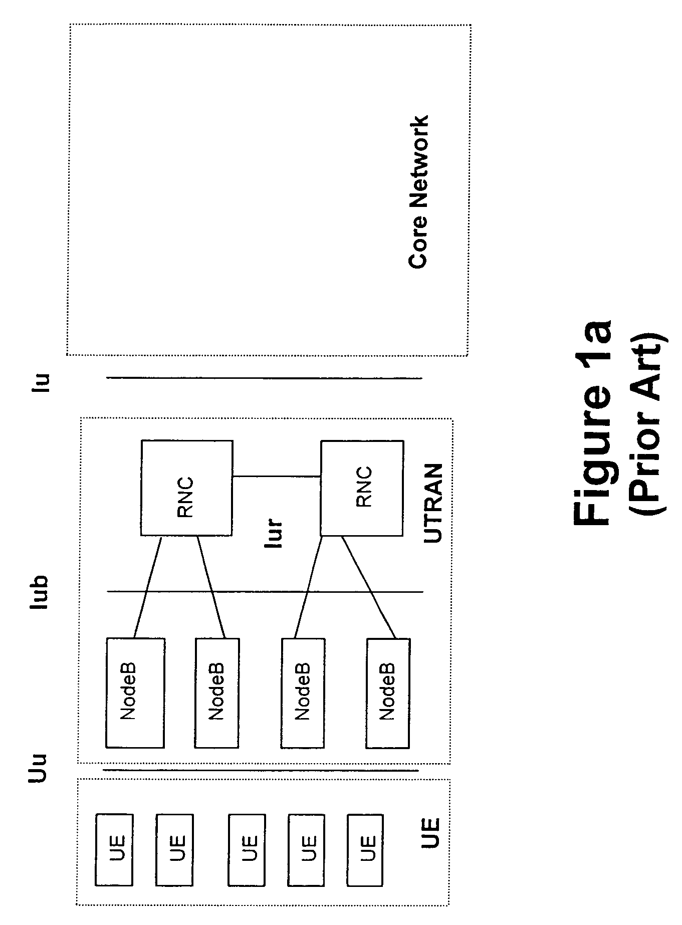
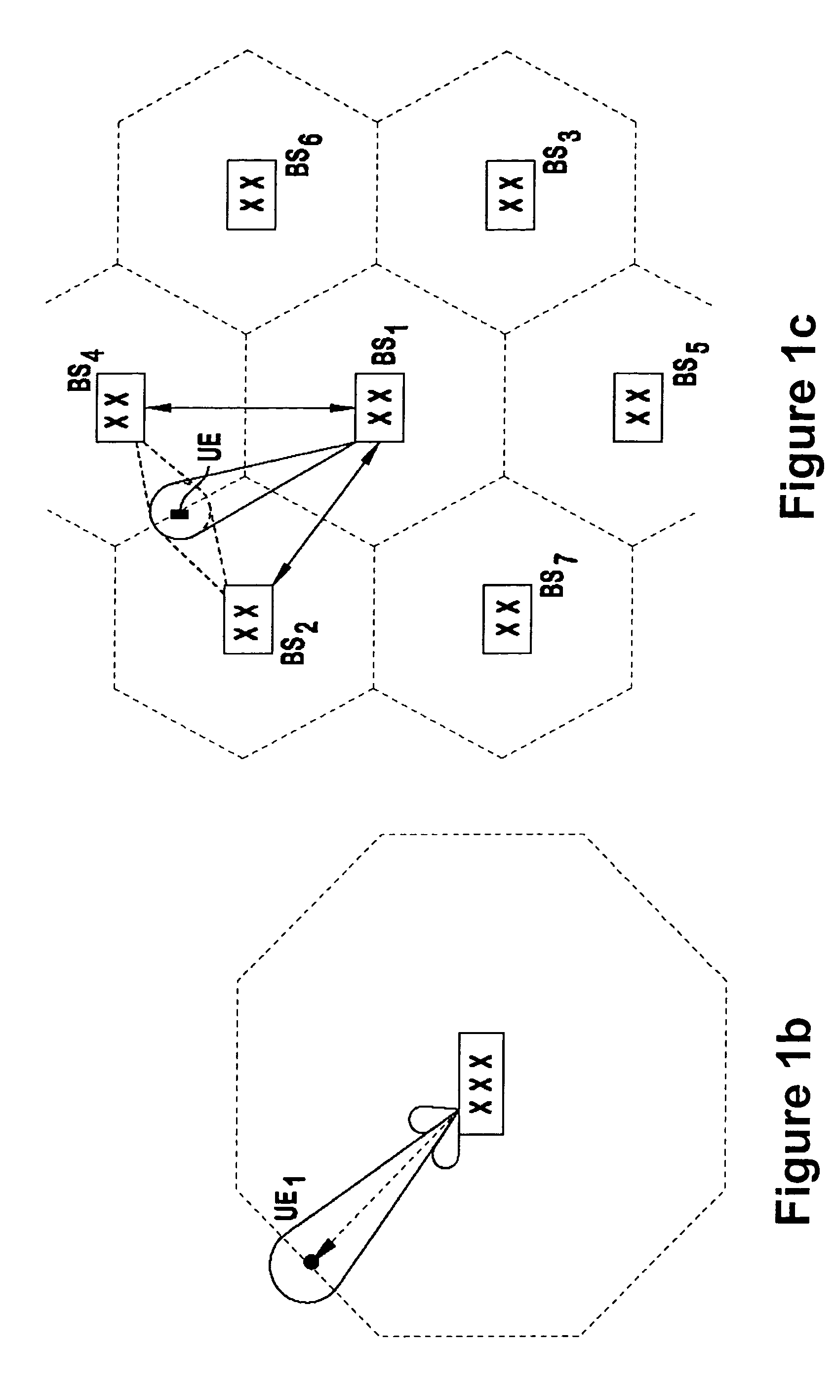
[0039]The present invention provides a wireless radio access network having networked base stations with an improved base station selection mechanism for mobile units, i.e. mobile WTRUs, as they enter and / or travel through the respective areas of geographic coverage provided by the respective base stations. Such mobile units, for example the UEs illustrated in FIG. 1a, generally include a transmitter, a receiver and a communication signal processor. The network preferably includes some type of base station interface that makes the selection. Such an interface for node Bs of ...


PUM


Abstract

Wireless mobile unit communication initiation is provided in a radio network that has a plurality of base stations, each providing wireless communication services in a respective geographic coverage. The wireless communication is established by first transmitting an omnidirectional sounding pulse from a wireless mobile unit. Information related to the detected sounding pulse is communicated to an interface by each base station detecting the sounding pulse. One of the base stations that detected the sounding pulse is selected for mobile unit communication based on the communicated information and directs a communication beam to the mobile unit to establish wireless communication. Alternatively, one or more of the base stations that detected the sounding pulse direct a communication beam to the mobile unit and the mobile unit selects unit the base station with which it is to establish wireless communication. Preferably, smart antennas, including directional beamforming capability, are employed by the base stations.

Description

CROSS-REFERENCE TO RELATED APPLICATION[0001]This application claims priority from U.S. Provisional Application No. 60 / 401,697, filed Aug. 7, 2002 which is incorporated by reference.FIELD OF THE INVENTION[0002]The present invention relates to mobile communication systems. More particularly, the present invention relates to wireless communication systems that supporting mobile unit communications and a method of increasing capacity through the use of base stations with beamforming or “smart” antennas.BACKGROUND OF THE INVENTION[0003]Wireless communication systems are well known in the art. Generally, such systems comprise communication stations which transmit and receive wireless communication signals between each other. Typically, base stations are provided which are capable of conducting wireless concurrent communications with a plurality of subscriber stations generically known as wireless transmit / receive units (WTRUs), which include mobile units. Generally, the term base station ...

Claims


Application Information

Patent Timeline
Patent Type & Authority Patents(United States)
IPC IPC(8): H04M1/00H04J13/00H04W4/02H04W16/28H04W36/08H04W48/14H04W48/20
CPCH04B7/0617H04W74/0891H04W4/02H04W16/28H04L25/0224
Inventor CAVE, CHRISTOPHERRUDOLF, MARIAN
Owner INTERDIGITAL TECH CORP
Why Eureka
Try Eureka