Lubricating structure

a technology of lubricating structure and notch plate, which is applied in the direction of gearing details, couplings, transportation and packaging, etc., can solve the problems of erroneous engagement of pocket plate and notch plate, and achieve the effect of reducing or eliminating the possibility of erroneous engagemen

Active Publication Date: 2018-03-29
TOYOTA JIDOSHA KK
View PDF5 Cites 4 Cited by
  • Summary
  • Abstract
  • Description
  • Claims
  • Application Information

AI Technical Summary

Benefits of technology

[0008]This disclosure is to reduce or eliminate the possibility of erroneous engagement of a selectable one-way clutch while lubricating the clutch.
[0010]With the above arrangement, high-viscosity lubricant that flows from the lubricant inlet flows along the inclined surface, and is discharged to the outside of the lubricant passage, through the opening formed in the inclined surface, because of its high viscosity. On the other hand, low-viscosity lubricant that flows from the lubricant inlet flows along the inclined surface, passes over the opening because of its low viscosity, and reaches the lubricant outlet, to be supplied into the selectable one-way clutch. As a result, it is possible to reduce or eliminate the possibility of erroneous engagement of the selectable one-way clutch, while lubricating the clutch.
[0012]With the above arrangement, the high-viscosity lubricant flows along the first protruding portion, and is guided to the opening, so that the lubricant can be easily discharged to the outside of the lubricant passage through the opening. On the other hand, the low-viscosity lubricant passes over the opening, after flowing along the first protruding portion. Thus, the low-viscosity lubricant is less likely or unlikely to be discharged through the opening, and a larger amount of the low-viscosity lubricant is supplied into the selectable one-way clutch.
[0014]With the above arrangement, even if a part of the high-viscosity lubricant passes over the opening, it is blocked and retained by the second protruding portion, and is less likely or unlikely to be supplied into the selectable one-way clutch. Thus, the part of the high-viscosity lubricant thus blocked and retained is discharged through the opening. Also, a possibility that the low-viscosity lubricant that has passed over the opening by use of the first protruding portion collides with the second protruding portion is reduced.
[0017]With this disclosure, in the lubricant passage, the high-viscosity lubricant that has flowed from the lubricant inlet drops, and flows along the inclined surface located on the lower side of the inlet in the direction of gravitation force. Then, when the lubricant reaches the opening formed in the inclined surface, it flows along an inner wall of the opening because of its high viscosity, and is discharged to the outside of the lubricant passage through the opening. On the other hand, the low-viscosity lubricant that has flowed from the lubricant inlet flows along the inclined surface, passes over the opening because of its low viscosity, and reaches the lubricant outlet, to be supplied into the selectable one-way clutch connected to the lubricant outlet. Thus, the high-viscosity lubricant is significantly restricted from being supplied into the selectable one-way clutch, while the low-viscosity lubricant is supplied into the selectable one-way clutch. Therefore, it is possible to reduce or eliminate the possibility of erroneous engagement of the selectable one-way clutch while lubricating the clutch.

Problems solved by technology

As a result, the selector plate is rotated by the dragging torque, and the pocket plate and the notch plate, which should be in the non-engaged state, may be erroneously engaged.

Method used


Image

  • Lubricating structure
  • Lubricating structure
  • Lubricating structure

Examples


first embodiment

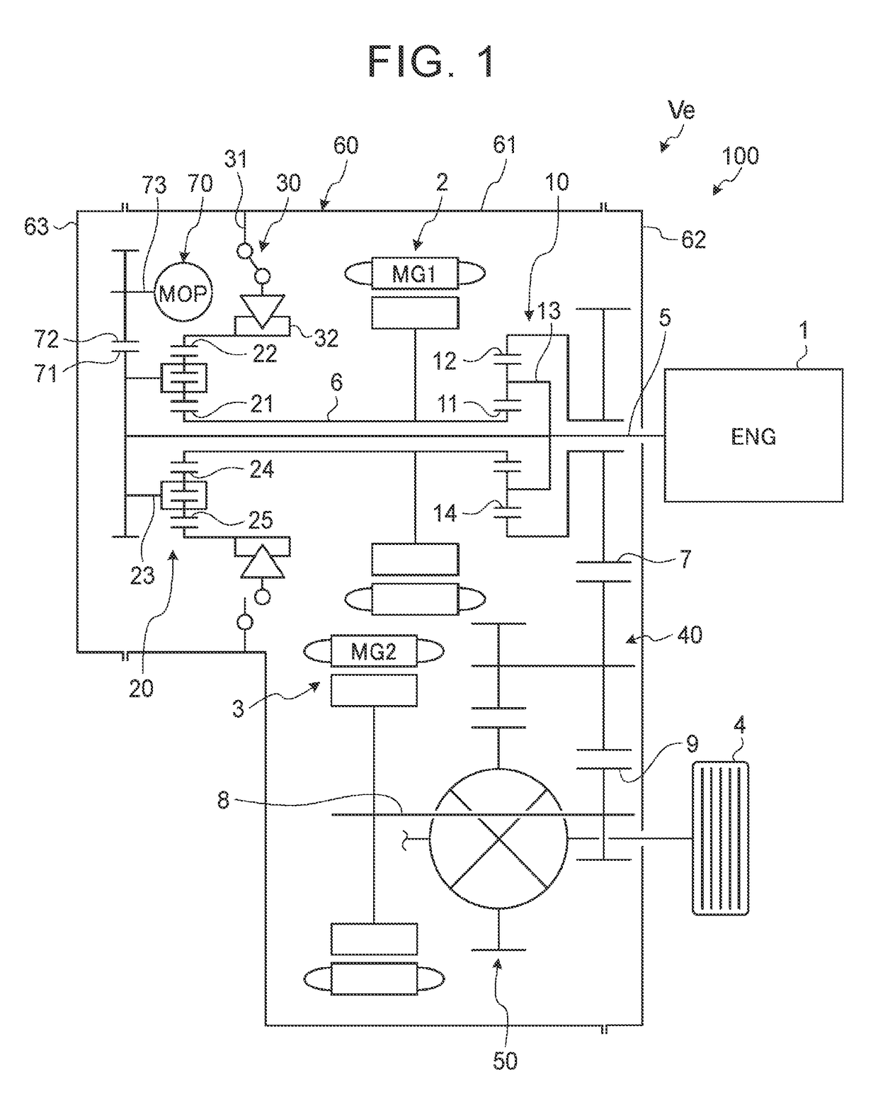
[0028]FIG. 1 is a skeleton diagram of a power transmission system of a vehicle in which a lubricating structure for a selectable one-way clutch is provided. The power transmission system 100 of the vehicle Ve includes an engine (ENG) 1 as a power source for running the vehicle, first motor (MG1) 2, second motor (MG2) 3, first planetary gear train 10 as a power split device, second planetary gear train 20 as a speed changing unit, selectable one-way clutch (which will be called “SOWC”) 30 as a gear lock mechanism, counter gear mechanism 40, and a differential gear mechanism 50. The engine 1 is provided by a known internal combustion engine. The first motor 2 and the second motor 3 are known motor-generators each having a motoring function and a power generating function, and are electrically connected to a battery (not shown) via an inverter (not shown).

[0029]In the power transmission system 100, power delivered from the engine 1 is divided by the first planetary gear train 10 and d...

second embodiment

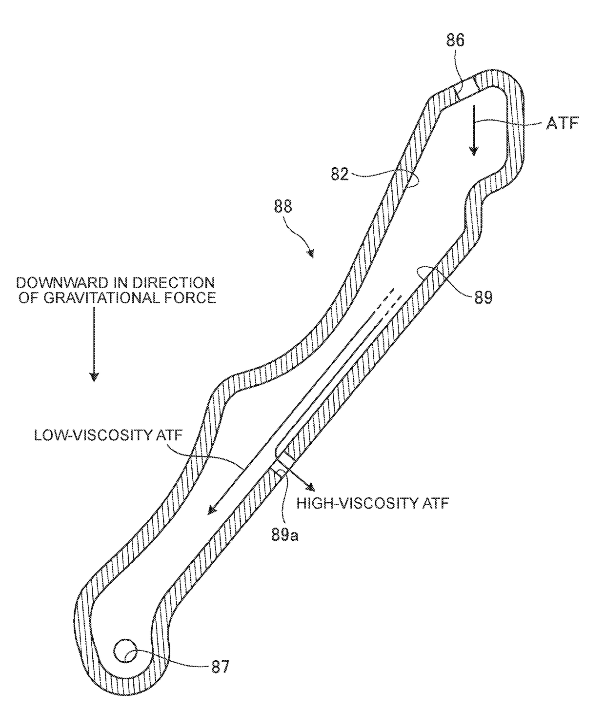
[0059]Referring now to FIG. 6, a preferable position of the opening 89Aa of the lubricant passage 88A in the direction of gravitational force in the second embodiment will be explained. In a condition where a sufficient amount of the low-viscosity ATF is supplied from the lubricant inlet 86, the low-viscosity ATF is accumulated in a portion of the lubricant passage 88A from the lubricant outlet 87 to the opening end 89Ab of the opening 89Aa located closest to the lubricant outlet 87. If the low-viscosity AFT is further supplied from the lubricant inlet 86 in this condition, it is discharged from the opening 89Aa. Accordingly, in the condition where a sufficient amount of the low-viscosity ATF is supplied, the height “h” from the lubricant outlet 87 to the opening end 89Ab of the opening 89a closest to the lubricant outlet 87 in the direction of gravitational force provides a pressure head, and a hydraulic pressure is generated in the low-viscosity ATF thus accumulated. This hydrauli...

third embodiment

[0066]Referring to FIG. 8, the relationship between the first protruding portion 89Bc and the second protruding portion 89Bd in the third embodiment will be described. Plane “S” including the opening end 89Bb of the opening 89Ba is specified for the sake of explanation. A distal end of the first protruding portion 89Bc will be referred to as “distal end P1”. Here, the distal end P1 of the first protruding portion 89Bc is a position in the first protruding portion 89Bc at which the height from the opening end 89Bb of the opening 89Ba (namely, the distance from the plane S) is maximized. Also, a distal end of the second protruding portion 89Bd will be referred to as “distal end P2”. Here, the distal end P2 of the second protruding portion 89Bd is a position in the second protruding portion 89Bd at which the height from the opening end 89Bb of the opening 89Ba (namely, the distance from the plane S) is maximized. While there are two or more locations corresponding to the distal end in ...


PUM


Abstract

A selectable one-way clutch includes a pocket plate, a notch plate, and a selector plate, and the selector plate is configured to rotate so as to switch the clutch between an engaged state and a non-engaged state. A lubricant passage through which a lubricant is supplied to the selectable one-way clutch has a lubricant inlet and a lubricant outlet, and the lubricant outlet is located on the lower side of the lubricant inlet in a direction of gravitational force, and connected to an inside of the selectable one-way clutch. The lubricant passage includes an inclined surface that is inclined with respect to the direction of gravitational force, between the lubricant inlet and the lubricant outlet, and the inclined surface has an opening.

Description

INCORPORATION BY REFERENCE[0001]The disclosure of Japanese Patent Application No. 2016-185943 filed on Sep. 23, 2016 including the specification, drawings and abstract is incorporated herein by reference in its entirety.BACKGROUND1. Technical Field[0002]The disclosure relates to a lubricating structure.2. Description of Related Art[0003]A hybrid vehicle (HV vehicle) that includes an engine and a motor as power sources, and is able to travel in an EV mode only with the motor while stopping the engine, is known. For example, a power transmission system of a hybrid vehicle disclosed in Japanese Patent Application Publication No. 2015-77846 (JP 2015-77846 A) includes a selectable one-way clutch as a lock mechanism, in a housing case (rear case).[0004]The selectable one-way clutch is attached to a rotating member, and includes a pocket plate, a notch plate, and a selector plate, which are arranged side by side in an axial direction of the rotating member. By rotating the selector plate b...

Claims


Application Information

Patent Timeline
Patent Type & Authority Applications(United States)
IPC IPC(8): F16H57/04
CPCF16H57/0424B60K6/383F16H57/0436F16H57/0476F16H57/0484F16H57/042F16H57/048B60K6/365B60K6/445Y02T10/62F16D41/084F16D2300/06
Inventor KUROSAKI, YUKISHIOIRI, HIROYUKITOMITA, MITSUAKIKATO, SHOTAROSHIBATA, HIROYUKI
Owner TOYOTA JIDOSHA KK
Why Eureka
Try Eureka