Heat collector plate for an electronic display

a technology of electronic display and collector plate, which is applied in the direction of electrical apparatus construction details, indirect heat exchangers, lighting and heating apparatus, etc., can solve the problems of insufficient heat dissipation systems of the past, which attempt to cool the entire interior of the display with fins and fans, and achieve the effect of improving conductive heat transfer

Inactive Publication Date: 2007-08-14
FRONTLINE SYST
View PDF9 Cites 11 Cited by
  • Summary
  • Abstract
  • Description
  • Claims
  • Application Information

AI Technical Summary

Benefits of technology

[0017]In a simple form, a heat collector of the present invention may include a heat sink. A liquid phase line and a gas phase line may be fluidly connected to each other and may be thermally connected to the heat sink. The heat collector may be for an electronic display and may include a heat sink in conjunction with a display screen of the electronic display. The heat sink

Problems solved by technology

This is not adequate in many climates.
With increased heat production with the screens of larger sizes and radiative heat transfer from the sun through th

Method used


Image

  • Heat collector plate for an electronic display
  • Heat collector plate for an electronic display
  • Heat collector plate for an electronic display

Examples


Embodiment Construction

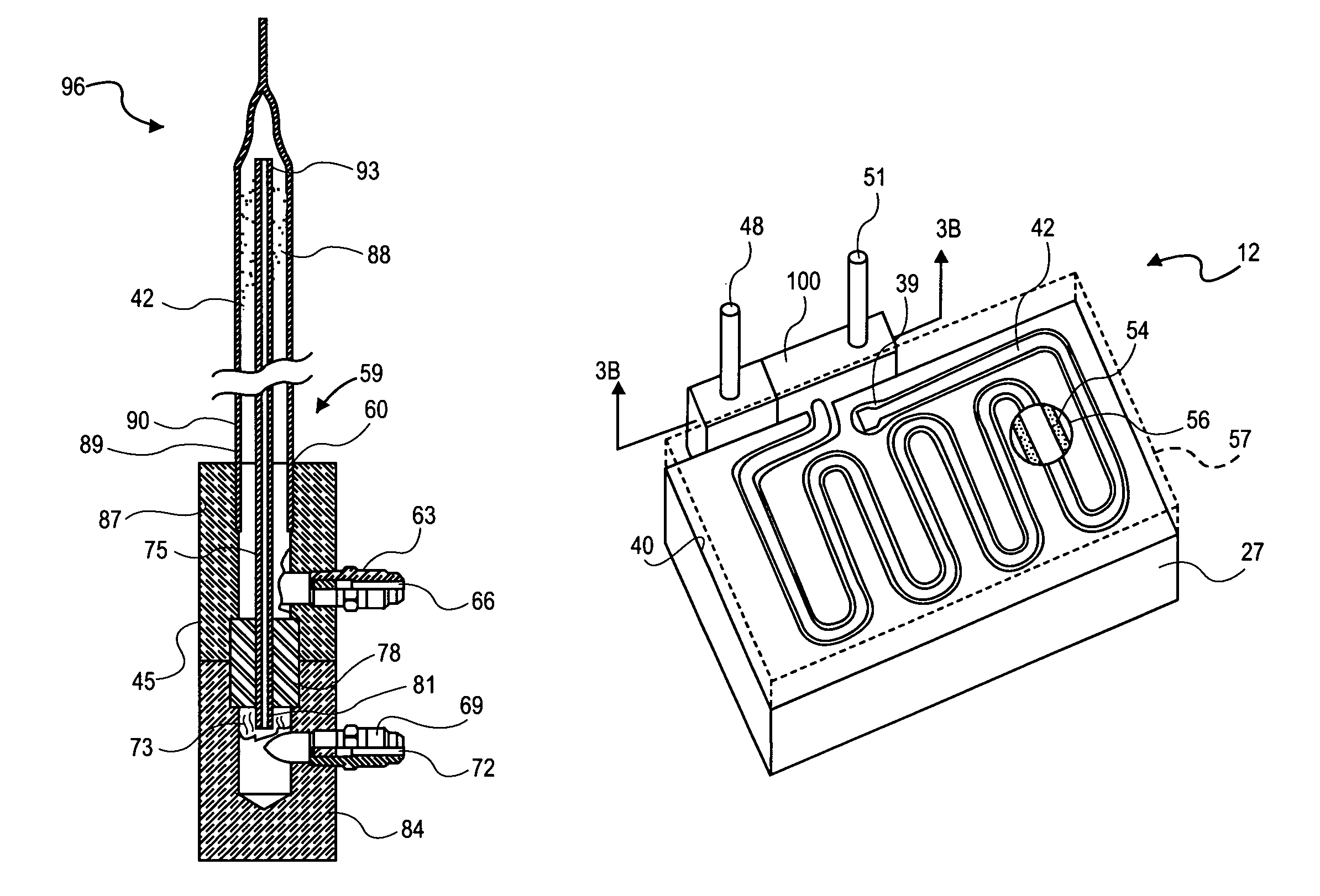
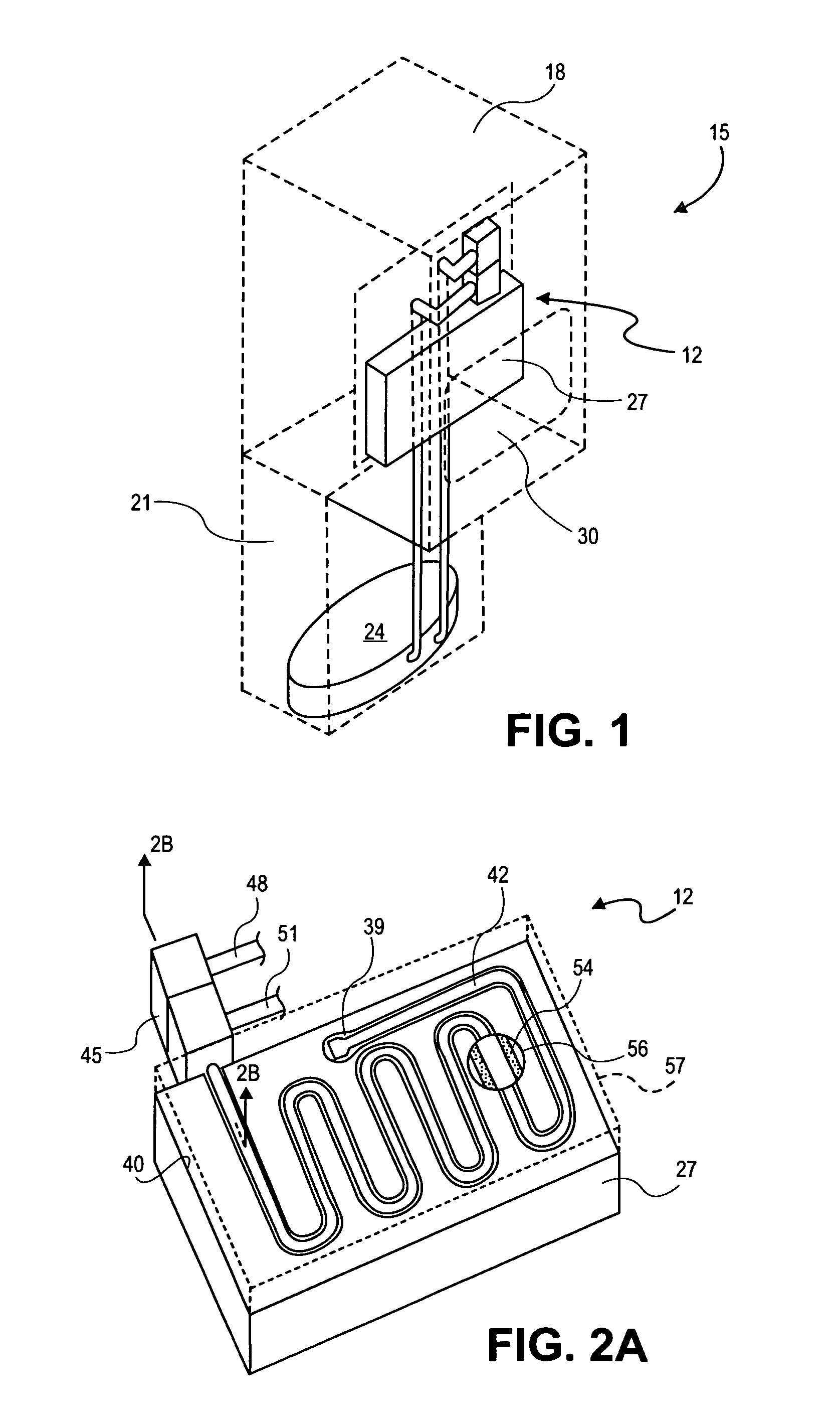
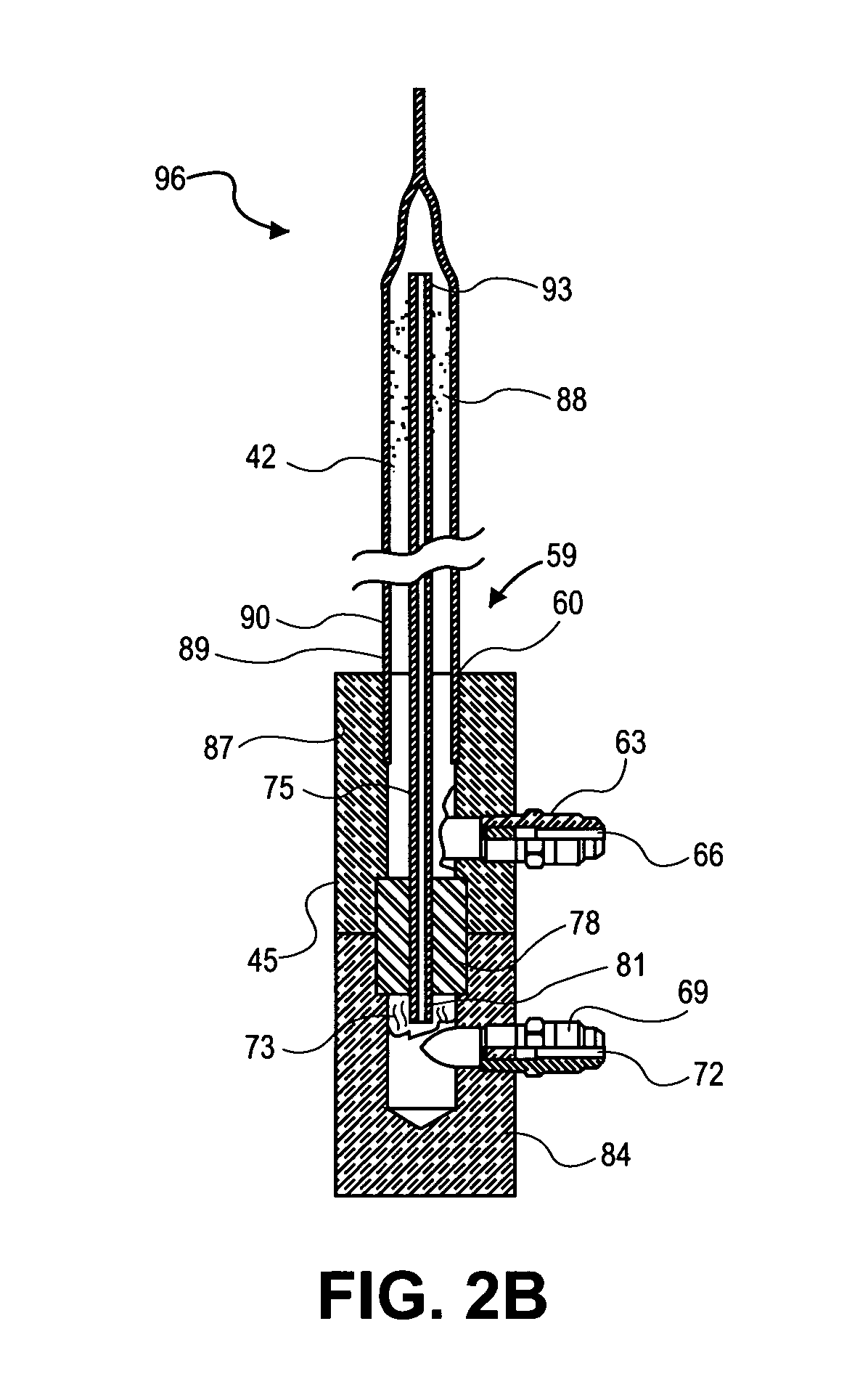
[0038]As discussed above, embodiments of the present invention relate to a heat collector plate for an electronic display. As shown in FIG. 1, a heat collector 12 may be provided in a display 15 in order to collect and remove excess heat from a compartment 18 and dissipate the excess heat in a location remote from the compartment 18, such as in a housing base 21. In the exemplary view of FIG. 1, the housing base 21 contains a compressor 24. The housing base will also typically include fins or other heat dissipating components and structure. The present invention also relates to a heat collector, which may including a heat collector plate, a base plate, and / or an electronic display.

[0039]As shown in FIG. 1, a heat collector 12 may be provided in a display 15 in order to collect and remove excess heat from a compartment 18 and dissipate the excess heat in a location remote from the compartment 18, such as in a housing base 21. In the exemplary view of FIG. 1, the housing base 21 conta...


PUM


Abstract

A heat collector includes a heat sink. A recess in the heat sink either forms or receives internal gas and liquid phase lines. A manifold may be integrally formed in the heat sink or may be added on. The manifold combines separate input and output connections into a composite input and output connection. An internal composite line may include the internal gas and liquid phase lines and may be connected to the composite connection of the manifold. The internal liquid phase line is fluidly connected to the internal gas phase line in a transition region of the composite line. Advantageously, the internal liquid phase line may be disposed inside the internal gas phase line for protection and positive heat transfer effects. A cover may hold the composite line in the recess and provide good thermal contact between the lines and the heat sink.

Description

BACKGROUND OF THE INVENTION[0001]1. Technical Field[0002]This invention generally relates to heat sinks for collecting heat, and in particular to a heat collector plate for an electronic display.[0003]2. State of the Art[0004]The prior art predominantly includes convective heat transfer systems for electronic displays.DISCLOSURE OF THE INVENTION[0005]The present invention relates to a heat collector plate for an electronic display. This invention has many features that are different from those of Applicant's own disclosure in U.S. Pat. No. 5,991,153, issued to Gregory S. Heady et al. Nov. 23, 1999 and entitled “Heat Transfer System for an Electronic Display”, the disclosure of which is incorporated herein in its entirety. However, much of the disclosure of U.S. Pat. No. 5,991,153 provides a background for the improvements of the present invention. Furthermore, the features of the present invention in combination with those of the prior patent represent significant and advantageous a...

Claims


Application Information

Patent Timeline
IPC IPC(8): H05K7/20F28D7/12
CPCF28D1/035F28D7/12H05K7/2099F28D2021/0029F28D2021/0031F28D2021/0064F28D15/025
Inventor HEADY, GREGORY S.
Owner FRONTLINE SYST
Why Eureka
Try Eureka