Fluorescence spectroscopic apparatus

a fluorescence spectroscopic and apparatus technology, applied in the field of fluorescence spectroscopy, can solve the problems of significant error in the measurement of the cross-correlation function, and the significant limitation of the selection of fluorescent dyes of fluorescent dyes with separate wavelengths, so as to reduce the adverse effect of measurement errors, limit the selection of fluorescent dyes, and eliminate the effect of measurement error adverse effects

Inactive Publication Date: 2008-02-26
OLYMPUS CORP
View PDF7 Cites 8 Cited by
  • Summary
  • Abstract
  • Description
  • Claims
  • Application Information

AI Technical Summary

Benefits of technology

[0028]If the fluorescence spectra of the two-color fluorescent dyes used overlap, possible crosstalk may result in a significant error in the measurement of the cross-correlation function. To avoid an error caused by crosstalk, the wavelengths of the two-color fluorescences are separated from each other as far as possible to reduce their adverse effects. In the example of an optical system introduced in Non-Patent Document 3, excitation light of 488 and 633 nm is used as a combination of such wavelengths. However, an attempt to use fluorescent dyes with separate wavelengths significantly limits the selection of fluorescent dyes.
[0029]The present invention has been made in view of these circumstances. An object of the present invention is to provide a fluorescence spectroscopic apparatus that can eliminate the adverse effect of measurement errors caused by crosstalk in spite of overlapping of emission spectra of fluorescent dyes.

Problems solved by technology

The major cause of the crosstalk is overlapping of emission spectra of the fluorescent dyes.
As a result, even if no interaction occurs between molecules labeled with ALEXA488 and molecules labeled with TAMRA, an erroneous analysis that about 10% of the molecules interact results.
If the fluorescence spectra of the two-color fluorescent dyes used overlap, possible crosstalk may result in a significant error in the measurement of the cross-correlation function.
However, an attempt to use fluorescent dyes with separate wavelengths significantly limits the selection of fluorescent dyes.

Method used


Image

  • Fluorescence spectroscopic apparatus
  • Fluorescence spectroscopic apparatus
  • Fluorescence spectroscopic apparatus

Examples


first embodiment

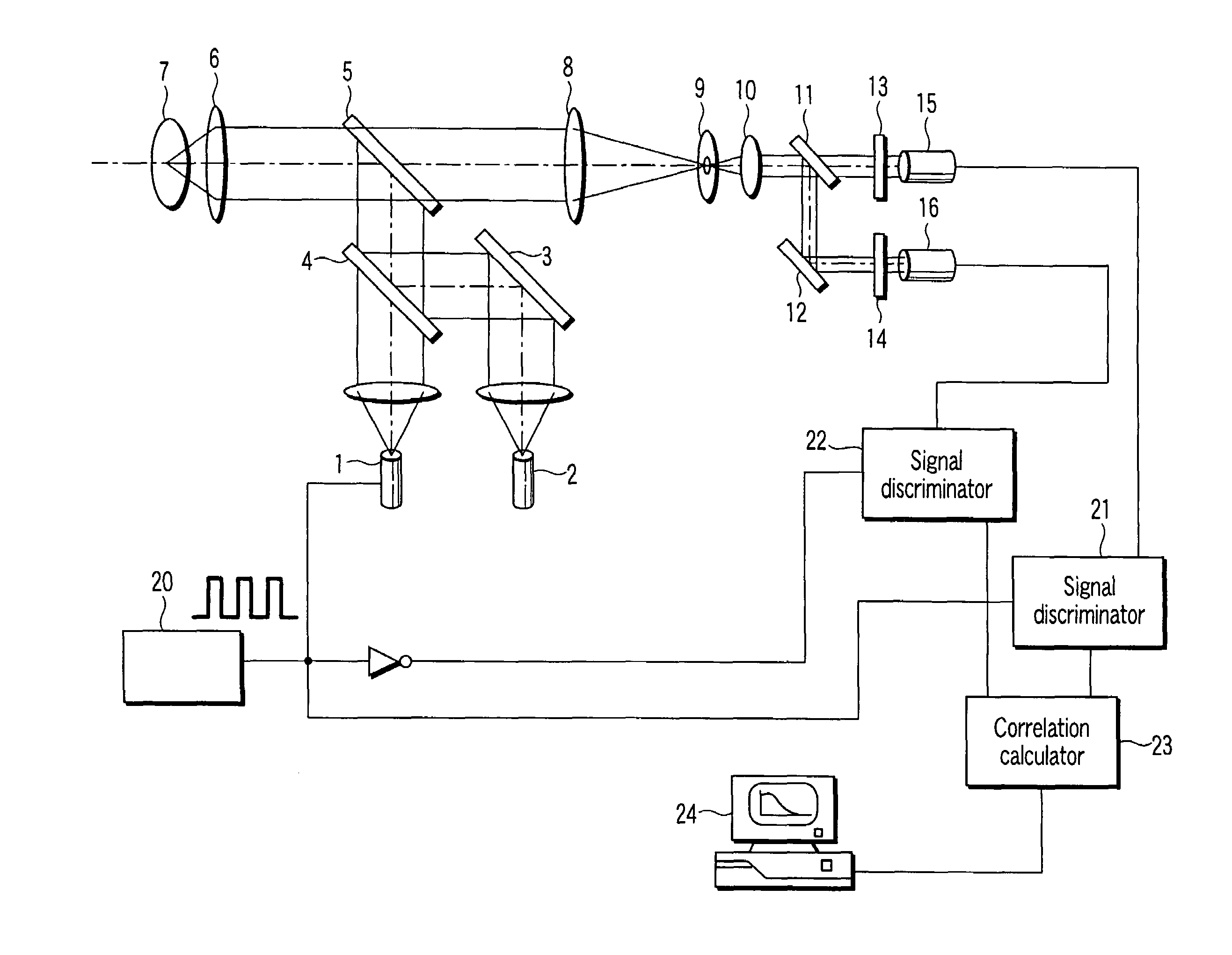
[0040]FIG. 1 is a diagram showing the configuration of a fluorescence spectroscopic apparatus according to a first embodiment of the present invention.

[0041]An excitation light source 1 is a blue laser light source that repeatedly turns on and off laser light at high speed in accordance with signals provided by a switching signal source, to output intermittent laser light. An excitation light source 2 is a green laser light source that repeatedly turns off and on depending on whether the excitation light source 1 is turned on or off, respectively, to output intermittent laser light. This repeated operation is performed at high speed; the operation is repeated at a period of, for example, 1 microsecond.

[0042]Intermittent laser light emitted by the excitation light sources 1 and 2 is mixed into a single light flux by a dichroic mirror 4. The light flux is reflected by a dichroic mirror 5 and then enters an objective lens 6. A sample 7 is placed at the focal position of the objective l...

second embodiment

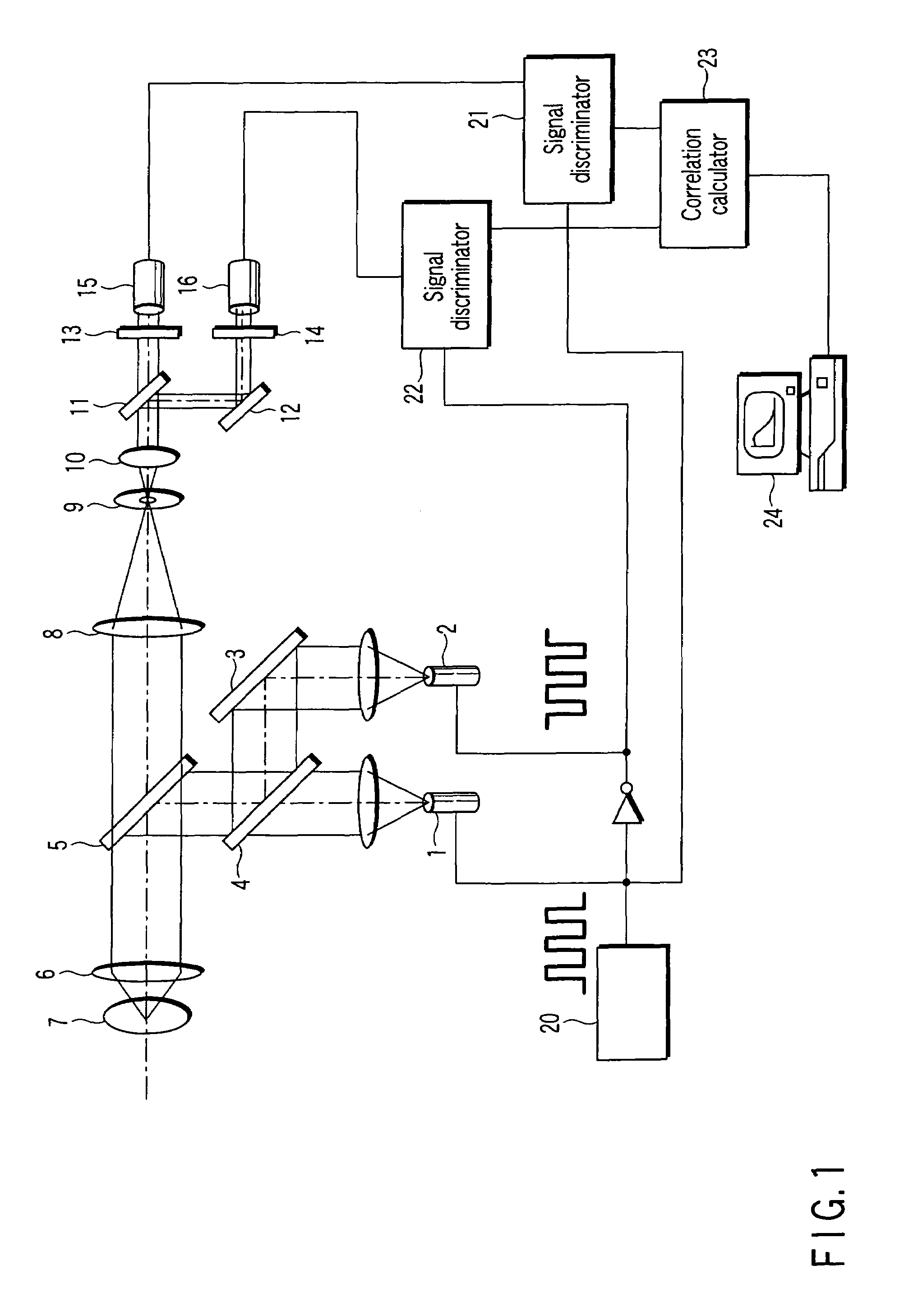
[0051]FIG. 2 is a diagram showing the configuration of a fluorescence spectroscopic apparatus according to a second embodiment of the present invention. The second embodiment is different from the first embodiment in that the signal discriminators 21 and 22, shown in FIG. 1, are not used but in that these processes are executed by the correlation calculator 23. Accordingly, parts having the same functions as those in the first embodiment are denoted by the same reference numerals, with their detailed description omitted.

[0052]Now, description will be given of the operation of the fluorescence spectroscopic apparatus of the second embodiment.

[0053]As is the case with the first embodiment, the blue excitation light source 1 and the green excitation light source 2 repeats turning on and off at high speed. Excitation light passes through a path similar to that in the first embodiment and enters the objective lens 6. The sample 7 is then irradiated with the excitation light; the sample 7...

third embodiment

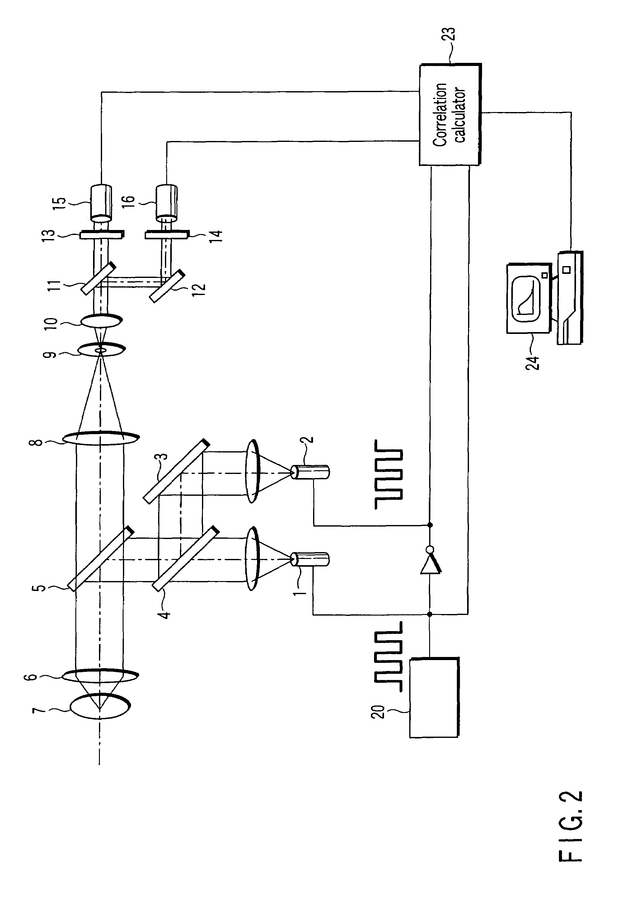
[0056]FIG. 3 is a diagram showing the configuration of a fluorescence spectroscopic apparatus according to a third embodiment of the present invention. The third embodiment is different from the first embodiment in that the excitation light source 2, shown in FIG. 1, is always on to continuously emit laser light. Accordingly, parts having the same functions as those in the first embodiment are denoted by the same reference numerals, with their detailed description omitted.

[0057]Now, description will be given of the operation of the fluorescence spectroscopic apparatus of the third embodiment.

[0058]As is the case with the first embodiment, the blue excitation light source 1 repeats turning on and off at high speed in accordance with signals provided by the switching signal source 20. On the other hand, the green excitation light source 2 is always on to continuously emit green excitation light. Excitation light passes through a path similar to that in the first embodiment and enters ...


PUM

PropertyMeasurementUnit
wavelengthsaaaaaaaaaa
wavelength bandaaaaaaaaaa

Abstract

There is provided a fluorescence spectroscopic apparatus includes an exciting optical unit configured to irradiate the same sample area with a plurality of excitation lights of different wavelength bands, an optical unit configured to repeatedly guide fluorescences emitted by the sample in response to the respective excitation lights, to a detection unit, and a calculation unit configured to perform analysis on the basis of a comparison of output signals corresponding to the fluorescences from the detection unit, wherein the exciting optical unit includes an excitation light varying unit configured to intermittently vary the intensity of at least one excitation light.

Description

CROSS REFERENCE TO RELATED APPLICATIONS[0001]This is a Continuation Application of PCT Application No. PCT / JP2005 / 005770, filed Mar. 28, 2005, which was published under PCT Article 21(2) in Japanese.[0002]This application is based upon and claims the benefit of priority from prior Japanese Patent Application No. 2004-096270, filed Mar. 29, 2004, the entire contents of which are incorporated herein by reference.BACKGROUND OF THE INVENTION[0003]1. Field of the Invention[0004]The present invention relates to a fluorescence spectroscopy of analyzing a fluctuation in fluorescent molecules in a biological sample to analyze the state of the fluorescent molecules, and a fluorescence spectroscopic apparatus that analyzes the interaction between different fluorescent molecules.[0005]2. Description of the Related Art[0006]Fluorescence correlation spectroscopy (FCS) is a technique for analyzing a fluctuation in light caused by Brownian motion of fluorescent molecules in a fine observation area ...

Claims


Application Information

Patent Timeline
Patent Type & Authority Patents(United States)
IPC IPC(8): G01N21/64
CPCG01N21/6408G01N21/6428G01N2021/6419G01N2021/6441
Inventor ISHIBASHI, KIYOCHIKAMIYAWAKI, ATSUSHI
Owner OLYMPUS CORP
Why Eureka
Try Eureka