
Fast encoding and decoding methods and related devices

a coding and decoding technology, applied in the field of digital communication, can solve the problems of limited bit rate of encoding and decoding process, limited encoding (respectively decoding) bit rate, and present transmission errors, and achieve the effect of not affecting performan

Active Publication Date: 2012-07-03
FRANCE TELECOM SA
View PDF9 Cites 0 Cited by
  • Summary
  • Abstract
  • Description
  • Claims
  • Application Information

AI Technical Summary

Benefits of technology

"The present invention provides an encoding and decoding method that can quickly and efficiently encode and decode data sequences without significant loss of performance compared to prior art methods. This is achieved by a method that parallelizes the encoding and decoding steps, reducing complexity and latency. The method includes a first coding step using a first code, an interleaving step, and a second coding step using a second code. The second coding step begins after a predetermined number of bits have been encoded by the first coding step. The method also includes a parity step that can be commenced without waiting for the end of the interleaving step. The interleaving step includes a bit level interleaving function that associates bits with interleaved bits. The method is effective in eliminating drawbacks of prior art methods and achieves performance exceeding or equaling that of prior art methods."

Problems solved by technology

If not, it detects that transmission errors are present.
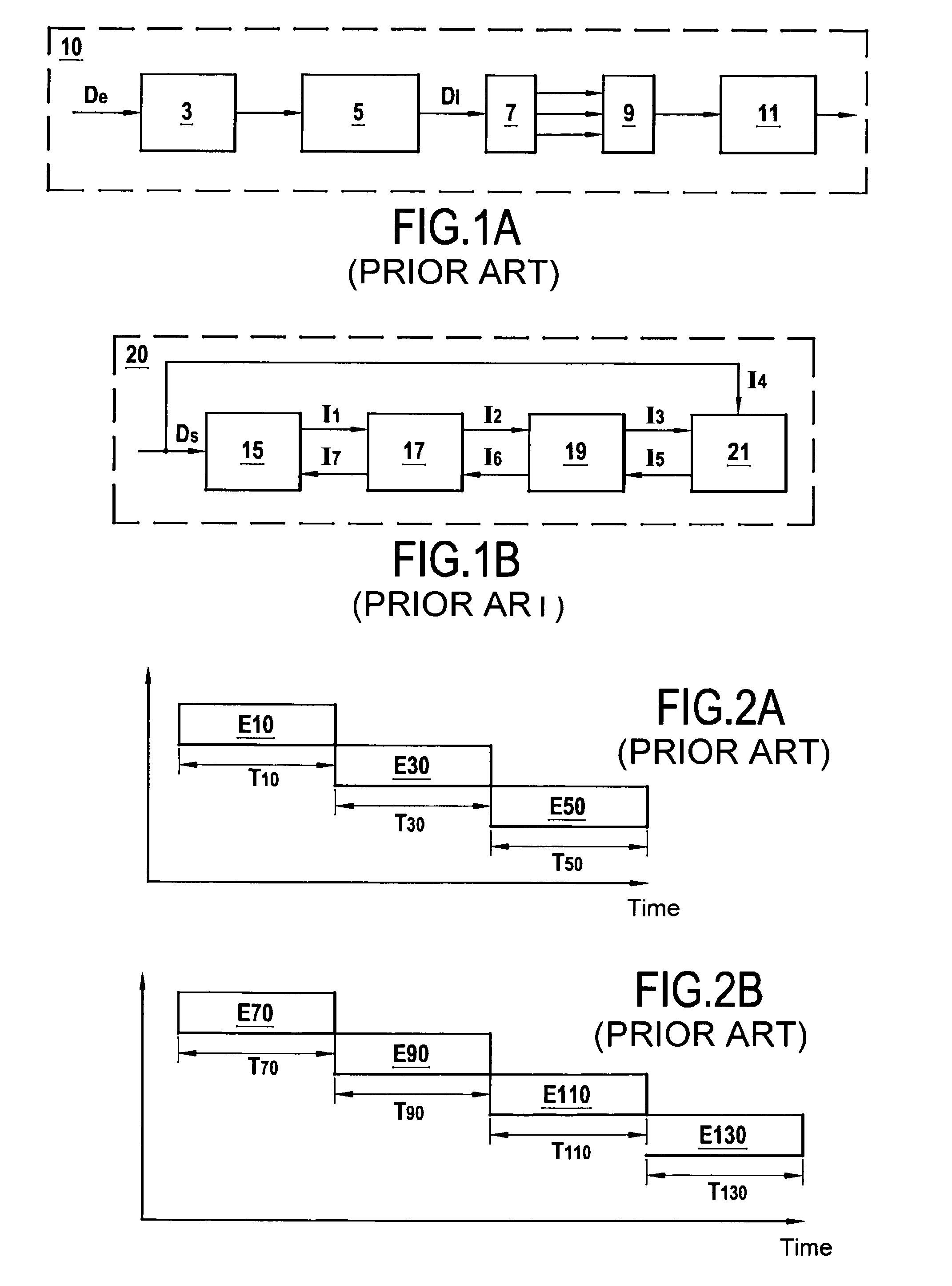
The major drawback of the encoder 10 (respectively decoder 20) is the latency introduced by its serial type architecture, the effect of which is to limit the encoding (respectively decoding) bit rate.
The bit rates of the encoding and decoding processes described above are limited because of how the various tasks constituting the encoding and decoding processes are scheduled.

Method used


Image

  • Fast encoding and decoding methods and related devices
  • Fast encoding and decoding methods and related devices
  • Fast encoding and decoding methods and related devices

Examples


Embodiment Construction

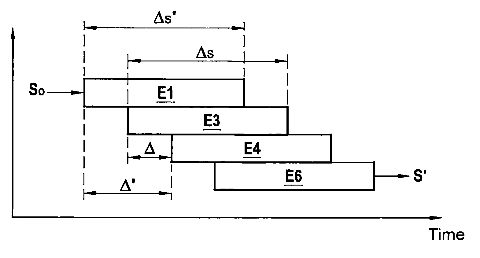
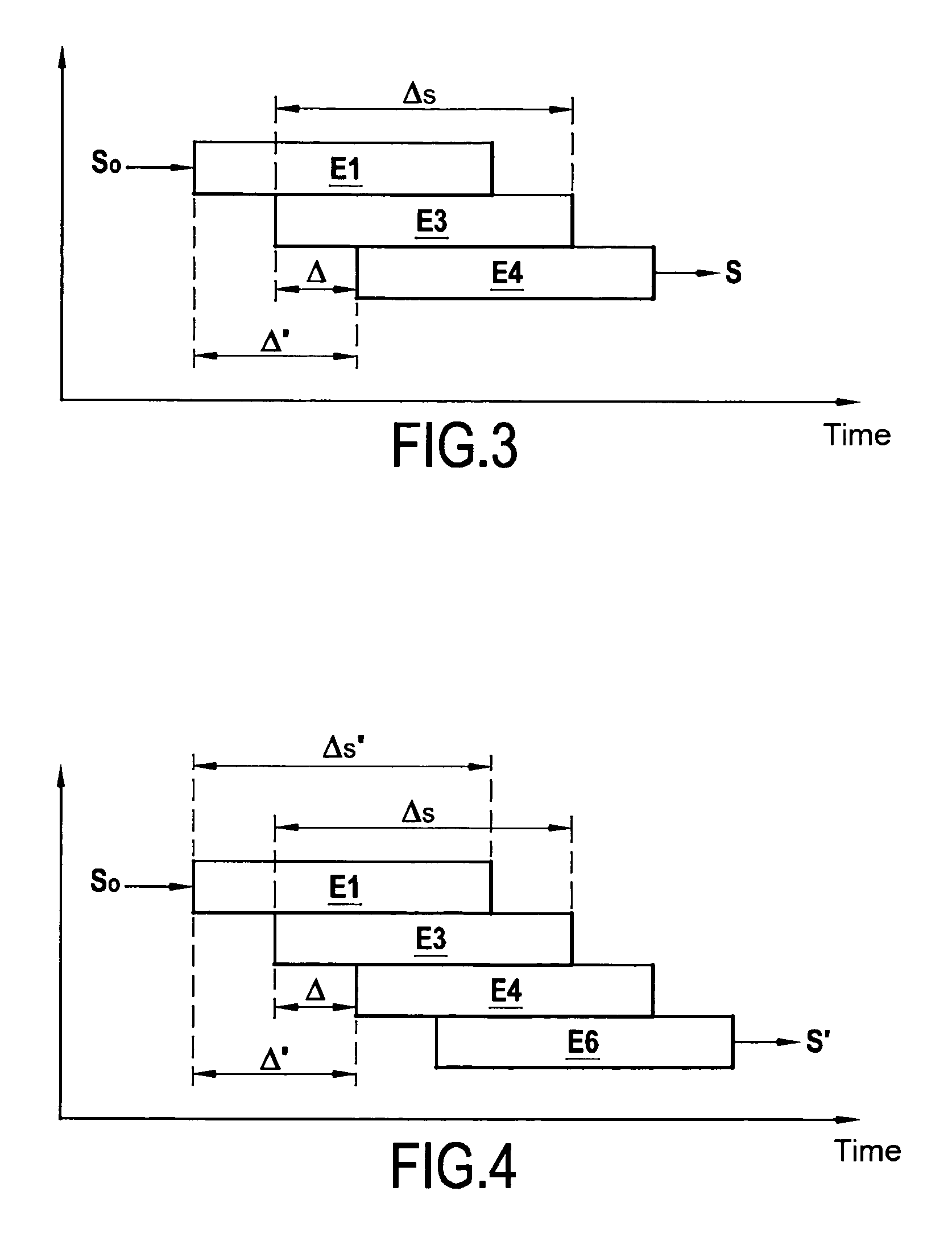
[0090]FIG. 3 shows the scheduling in time (abscissa axis) of the steps (ordinate axis) of an encoding method of the invention for encoding an input bit sequence S0 to yield a coded bit sequence S.

[0091]This method includes a first coding step E1 applied to the bits of the input bit sequence S0, using a first code. The bits produced by this first coding step are interleaved by interleaving means 33 (see FIG. 6) during an interleaving step E3.

[0092]The bits coming from the interleaving means 33 are encoded in a second coding step E4 referred to as a parity step using a second code to generate the coded bit sequence S.

[0093]The parity, second coding step E4 advantageously begins after interleaving a predetermined number Δ of bits. This predetermined number Δ of bits is between a first lower number Δi of bits depending on one or more parameters of the interleaving step E3 and a first higher number Δs of bits corresponding to the total number of bits to be processed during the interleavi...


PUM


Abstract

A method of low latency encoding of an input bit sequence (S0) to yield an encoded bit sequence (S), and a corresponding decoding method, said encoding method including: a first encoding step (E1) applied to bits of the input bit sequence (S0), using a first code; an interleaving step (E3) in which an interleaver interleaves the bits obtained from said first code; and a parity, second encoding step (E4) applied to the bits obtained from said interleaver, using a second code, to generate said encoded bit sequence (S). The parity, second encoding step (E4) starts after a predetermined number Δ of bits have been interleaved, said predetermined number Δ of bits ranging between a first lower number Δi of bits depending on one or more parameters of said interleaving step (E3) and a first higher number Δs of bits corresponding to the total number of bits to be processed during said interleaving step (E3).

Description

RELATED APPLICATIONS[0001]This is a U.S. National Phase Application under 35 USC 371 of International Application PCT / FR2007 / 050664, filed on Jan. 18, 2007.[0002]This application claims the priority of French application no. 06 / 50196 filed on Jan. 19, 2006, and the content of which is hereby incorporated by reference.TECHNICAL FIELD OF THE INVENTION[0003]The invention relates to the field of digital communications and is more particularly concerned with a high bit rate encoding and decoding method using an LDPC (low density parity check) code, for example, and associated encoding and decoding devices.BACKGROUND OF THE INVENTION[0004]At present, the highest performing digital communications systems are based on systems in which data to be transmitted is protected by very high performance channel coding and is decoded iteratively by a weighted output decoder. Channel coding or error corrector coding improves transmission quality by inserting redundant bits into the message to be trans...

Claims


Application Information

Patent Timeline
Patent Type & Authority Patents(United States)
IPC IPC(8): H03M13/00
CPCH03M13/1194H03M13/2771H03M13/2972H03M13/2978H03M13/6566
Inventor DORE, JEAN-BAPTISTEHAMON, MARIE-HELENEPENARD, PIERRE
Owner FRANCE TELECOM SA
Learn More