Pre-assembled hip, ridge or rake shingle

a ridge or rake technology, applied in the field of shingle art, can solve the problems of apex of a roof, inability to bend a shingle to cover, cracks can form, etc., and achieve the effect of facilitating the opening of the hinge and facilitating the stacking of the shingles

Inactive Publication Date: 2012-07-10
CERTAINTEED CORP
View PDF17 Cites 16 Cited by
  • Summary
  • Abstract
  • Description
  • Claims
  • Application Information

AI Technical Summary

Benefits of technology

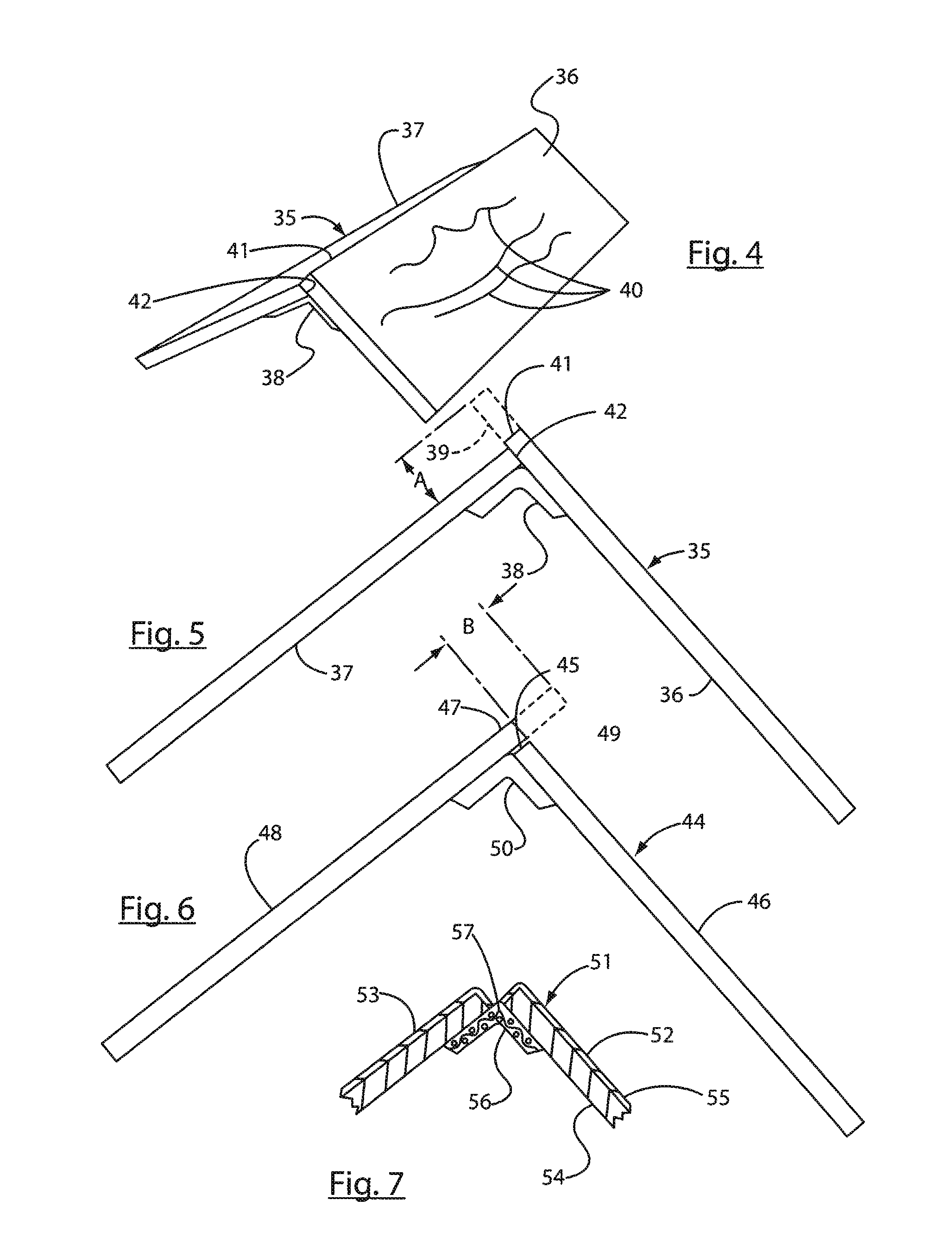
[0013]It is a further object of this invention to accomplish the above objects, wherein the relatively rigid panels are connected together by a layer of release tape across the hinge-like portion, to facilitate stacking of the shingles in substantially flattened condition, or to facilitate the openability of the hinge to accommodate various potential angles between the panels in the installed condition of shingles on a roof.

Problems solved by technology

In bending such shingle, generally when it is of the manufactured asphalt shingle type, it is possible that, as the shingle is bent to have an included angle between surfaces thereof, to partially cover each surface of the roof as well as the apex of the roof, cracks can form.
In instances where the shingles are substantially rigid, such as resembling slate, tile, shakes or the like, it is often not practical to bend a shingle to cover the surfaces on each side of the apex of a roof.

Method used


Image

  • Pre-assembled hip, ridge or rake shingle
  • Pre-assembled hip, ridge or rake shingle
  • Pre-assembled hip, ridge or rake shingle

Examples


Embodiment Construction

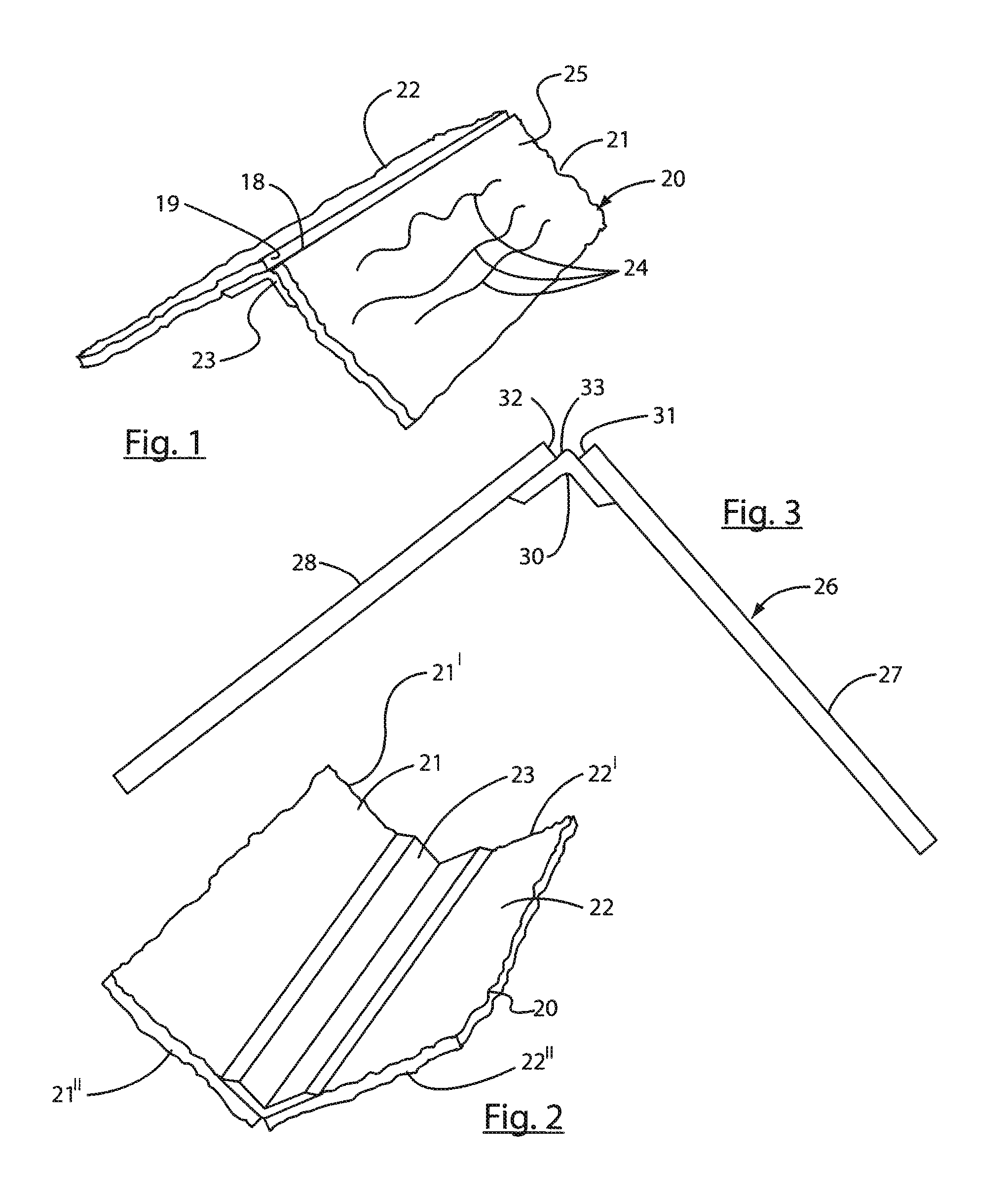
[0028]Referring now to the drawings in detail, reference is first made to FIG. 1, wherein a shingle 20 in accordance with this invention is illustrated as having a pair of substantially rigid planar panels 21 and 22 having opposite ends 21′, 21″, 22′, 22″ as shown in FIGS. 1 and 2, and which are connected together by a hinge 23 that is softer, relatively more flexible than the substantially ridge-like planar panels, to facilitate bending to different angles as may be required with the hinge being co-extensive between said opposite ends 21′, 21″, 22′, 22″ of said rigid planar panels 21 and 22 as is shown in FIG. 2. The relatively flexible hinge 23 in the embodiment of FIG. 1 is of a separate structure, or different material than panels 21 and 22 and can be rubber-like or elastomeric.

[0029]A plurality of relief zones or areas 24 are provided on the upper exterior surface 25 of the shingle 20, simulating natural slate, tile, or shake, such as cedar shake, shingles or the like, with the...


PUM

PropertyMeasurementUnit
cycle timeaaaaaaaaaa
hold timeaaaaaaaaaa

Abstract

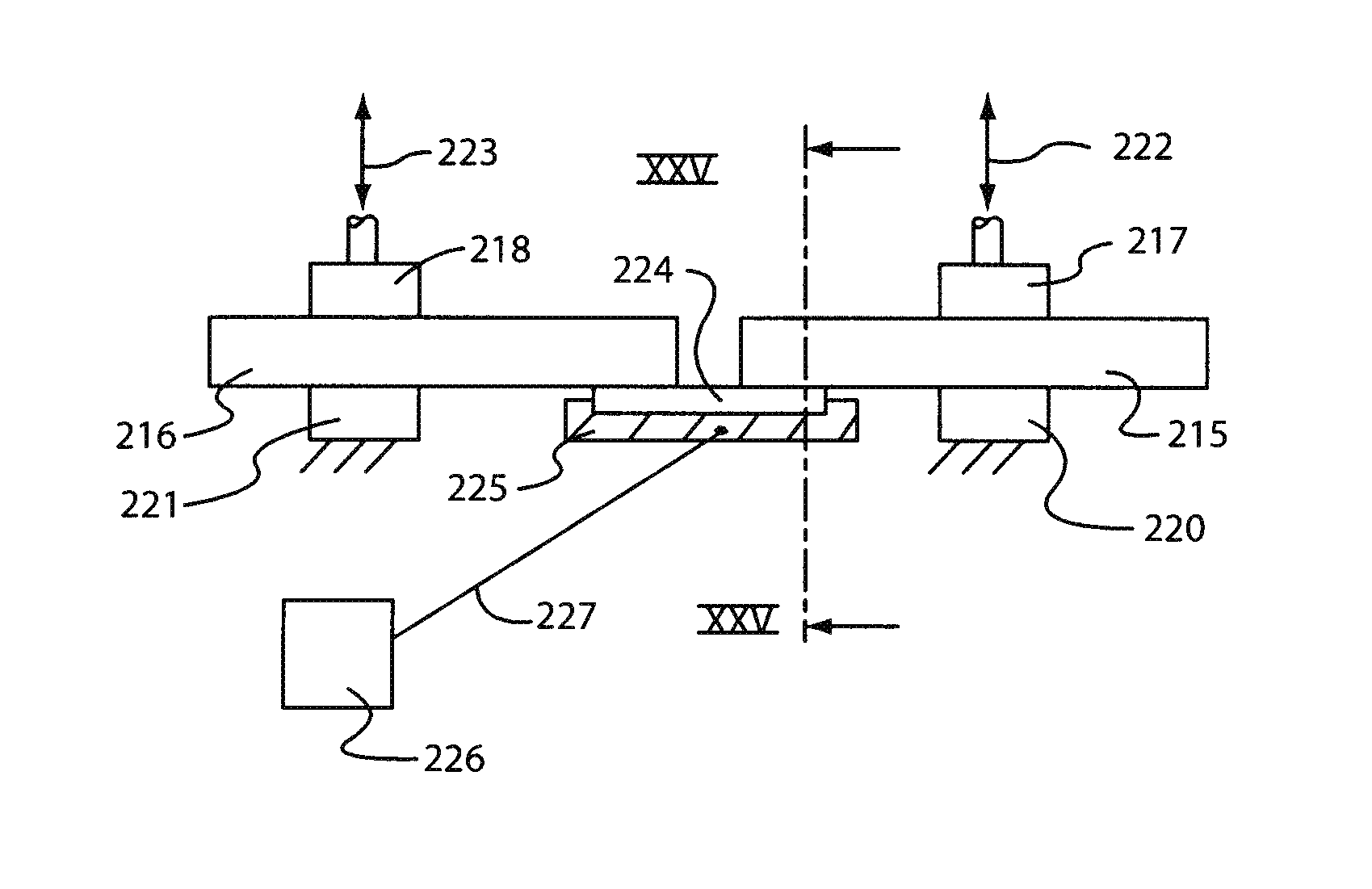
A hip, ridge or rake shingle is provided, in which a pair of substantially rigid panel portions are connected by a hinge portion, and wherein the shingle is pre-assembled, but can conform to a variety of different angles to accommodate different angular relationships between surfaces of a hip, ridge or rake of a roof. The substantially rigid panel portions are connected by a hinge and may or may not have a reinforcement member, and all of the panels, hinges and reinforcement members are of synthetic thermoplastic polymeric construction and are welded together by ultrasonic or vibratory welding techniques.

Description

CROSS-REFERENCE TO RELATED APPLICATIONS[0001]This is a continuation-in-part of U.S. application Ser. No. 11 / 689,574, filed Mar. 22, 2007, the complete disclosure of which is herein incorporated by reference.BACKGROUND OF THE INVENTION[0002]It is known in the shingle art that shingles that are applied to a roof are generally applied in courses, running up the slope of a roof, toward the apex or ridge of the roof.[0003]For example, in applying shingles to different sloped surfaces of a roof, wherein those sloped surfaces meet at an apex, the various courses of shingles on each side of the apex are increasingly disposed up each slope, until the apex or ridge of the roof is reached. At that point, it is desirable to provide a shingle that is a unitary structure that overlies a portion of each sloped surface of the roof, including the apex of the roof.[0004]Sometimes, a piece of shingle is cut to be applied over the shingles on each sloped surface, and over the apex, in an inverted “V” m...

Claims


Application Information

Patent Timeline
Patent Type & Authority Patents(United States)
IPC IPC(8): B32B37/00
CPCE04D1/20E04D1/30E04D2001/305
Inventor KALKANOGLU, HUSNU M.JACOBS, GREGORY F.SHAY, ERIK F.PLACHE, ALEXANDER H.
Owner CERTAINTEED CORP
Why Eureka
Try Eureka