Wind channel model tail support rod structure capable of actively damping vibration

A technology of active vibration reduction and tail strut, which is applied in the testing of machine/structural components, aerodynamic tests, measuring devices, etc. It can solve the problems of inconvenient installation and maintenance, complex active vibration reduction structure of piezoelectric stack, etc. Achieve fast response, good usability and maintainability, and good openness

Active Publication Date: 2013-09-04
NANJING UNIV OF AERONAUTICS & ASTRONAUTICS
View PDF4 Cites 35 Cited by
  • Summary
  • Abstract
  • Description
  • Claims
  • Application Information

AI Technical Summary

Problems solved by technology

Because the active damping structure needs to connect the piezoelectric stack structure with the strain gauge balance, not only the design of the strut structure but also the structure of the balance must be modified during application; in addition, the entire piezoelectric stack active control surface In the model, affected by the size and structure of the piezoelectric stack, the size of the model, balance and tail rod is required to be relatively large, so this structure is suitable for vibration reduction of large-scale or full-scale blower models; finally, the piezoelectric stack actively The vibration damping structure is complex, and the entire piezoelectric stack structure is installed in the model, which makes it very inconvenient to install and maintain during use, which is also the shortcoming of the structure

Method used


Image

  • Wind channel model tail support rod structure capable of actively damping vibration
  • Wind channel model tail support rod structure capable of actively damping vibration
  • Wind channel model tail support rod structure capable of actively damping vibration

Examples


Embodiment Construction

[0027] The present invention will be further described below in conjunction with accompanying drawing:

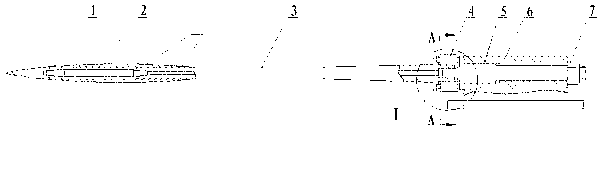
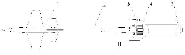
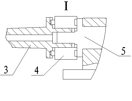
[0028] Figure 1 to Figure 5 is the assembly relationship of the entire tail strut damping structure, figure 1 It is the front view of the present invention, figure 2 It is a top view of the present invention, a model 1 is installed on the front section 3 of the tail strut of the present invention, a strain gauge balance 2 is installed inside the model 1, and the rear section 5 of the tail strut is fixed on the support 6 by a lock nut 7, and it is characterized in that: The front section 3 of the tail strut and the rear section 5 of the tail strut are connected through the hole shaft, and a pair of symmetrically connected flanges are respectively located on the front section 3 of the tail strut and the rear section 5 of the tail strut. There are four positioning slots with an included angle of 90° on the flange respectively, and piezoelectric stacks 4 are connected betwe...


PUM


Abstract

The invention provides a wind channel model tail support rod structure capable of actively damping vibration by utilizing a piezoelectric stack. The front end of the tail support rod is used for mounting a model internally provided with a strain meter balance, and the rear end of the tail support rod is fixed on a support seat by a locking nut; the tail support rod is divided into a front tail support rod section and a rear tail support rod section, which are connected by a hole shaft in a match mode; a pair of symmetrically connected flange plates in the connecting part are positioned at the front and rear tail support rod sections respectively; and four positioning slots, mutually forming an included angle of 90 degrees, are arranged on the two flange plates and are provided with the piezoelectric stack. Compared with the traditional passive vibration damping structure, the wind channel model tail support rod structure capable of actively damping vibration has the advantages of high frequency and fast responding as adopting the intelligent piezoelectric material as a vibration damping element, can effectively control the vibration, has no effect on the flow field of a test model as the whole vibration damping part is small in size, is simple in structure and design and suitable for the vibration damping of tail support rod structures in different sizes, and has better usability and maintainability.

Description

technical field [0001] The invention relates to a wind tunnel model strut structure, in particular to an active damping wind tunnel model tail strut structure. Background technique [0002] In a conventional wind tunnel force test, the wind tunnel test model and its fixtures constitute a cantilever beam system. The cantilever beam system consists of a test model, a strain gauge balance, a tail rod and a bracket. The test model is located at the front end, the strain gauge balance is fixed in the model, the model is installed on the slender tail rod, and the tail rod is fixed on the bracket. superior. In this way, during the wind tunnel test, the model is subjected to unsteady aerodynamic force, and vibrates together with the balance, tail strut and support. This kind of vibration not only affects the accuracy of the test data, but also easily causes the support system to resonate because the aerodynamic force is a broadband excitation load. If the vibration time is too lo...

Claims


Application Information

Patent Timeline
Patent Type & Authority Applications(China)
IPC IPC(8): G01M9/04
Inventor 李杰锋沈星杨学永王鑫伟姜文骏
Owner NANJING UNIV OF AERONAUTICS & ASTRONAUTICS
Why Eureka
Try Eureka