Method for real-time synchronization and dynamic compensation between chain Ethernet nodes

A real-time synchronization and dynamic compensation technology, applied in synchronization devices, digital transmission systems, electrical components, etc., can solve problems such as distributed clock offset, and achieve the effect of reducing synchronization jitter, less software and hardware resources, and good openness

Active Publication Date: 2011-11-09
山东易码智能科技股份有限公司
View PDF4 Cites 36 Cited by
  • Summary
  • Abstract
  • Description
  • Claims
  • Application Information

AI Technical Summary

Problems solved by technology

[0007] The purpose of the present invention is to solve the problem of distributed clock offset and synchronization jitter caused by network equipment delay, system crystal oscillator error and drift between nodes when chained Ethernet is used for field-level communication, and to provide a chained Ethernet between nodes The real-time synchronization and dynamic compensation method, which is simple, takes up less software and hardware resources, and lowers the cost

Method used


Image

  • Method for real-time synchronization and dynamic compensation between chain Ethernet nodes
  • Method for real-time synchronization and dynamic compensation between chain Ethernet nodes
  • Method for real-time synchronization and dynamic compensation between chain Ethernet nodes

Examples


Embodiment Construction

[0034] The present invention will be further described below in conjunction with the accompanying drawings and embodiments.

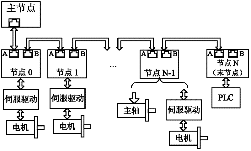
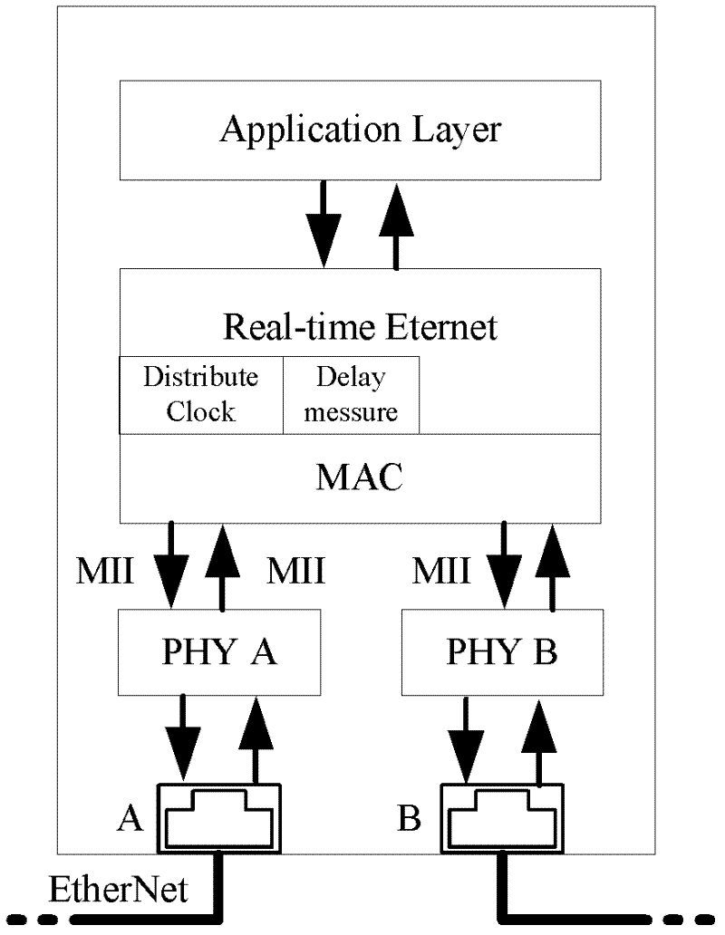
[0035] In a chained Ethernet network, at least one master node and several slave nodes are included. Each slave node contains at least two hubs composed of network ports. The master node and slave nodes and each slave node are connected end to end through standard crossover cables to form a chain network structure, such as figure 1 shown. The steps of synchronization and dynamic compensation between distributed nodes are as follows:

[0036] 1. After the system power-on self-test. The master node starts to enumerate each slave node, assigns a node number to the slave node, and obtains the node type of each slave node.

[0037] 2. After the enumeration is completed, the first node in the slave nodes starts the cycle timer as the 0 node and starts to implement the management of the bus cycle. When the timer counts down to the communication period, no...


PUM


Abstract

The invention discloses a method for real-time synchronization and dynamic compensation between chain Ethernet nodes. The method is simple, convenient and lower in cost, and fewer software and hardware resources are occupied. The method comprises the following steps that: 1, a master node starts enumerating each slave node; 2, a zero node which is the first of the slave nodes starts a cycle timer, and implements management over a bus cycle in a way of cyclically transmitting a synchronization packet; 3, the synchronization packet starts delay measurement modules of the slave nodes for timing, and is continuously transmitted until being transmitted to the last slave node; 4, the last node constructs and uploads a standard Ethernet data packet; 5, each slave node stops the timing when receiving a returned packet, and starts a local distributed clock by taking a half of a measured value as an initial value; and 6, after completely receiving control data, the slave nodes generate synchronous signals when the time of each synchronization clock is the same, execute corresponding operations, latch a current state and wait for uploading.

Description

technical field [0001] The invention relates to a real-time synchronization and dynamic compensation method between chained Ethernet nodes. Background technique [0002] The industrial control network has developed from DCS (Distributed Control System) to FCS (Fieldbus Control System) until today, and industrial Ethernet technology has become the future development direction. On the one hand, the Ethernet topology is flexible and supports various structures such as chain, star, mesh and daisy chain, which can easily realize the interconnection of intelligent devices in the workshop, and its bandwidth of 100M, 1000M or even higher It is enough to guarantee the exchange of massive data between smart devices. On the other hand, the enterprise information management system can be easily connected to the workshop network through the Ethernet gateway to realize the vertical consistency of the upstream enterprise management system and field devices on the network. Therefore, indu...

Claims


Application Information

Patent Timeline
Patent Type & Authority Applications(China)
IPC IPC(8): H04L7/00
Inventor 姬帅张承瑞
Owner 山东易码智能科技股份有限公司
Why Eureka
Try Eureka