Magnetic head for perpendicular magnetic recording having a main pole and two shields

a perpendicular magnetic and magnetic recording technology, applied in the direction of magnetic recording heads, data recording, instruments, etc., can solve the problem that there have been no attempts to reduce the length of the magnetic path that passes through the main pole and the trailing shield, and achieve the effect of reducing the length of the magnetic path

Active Publication Date: 2012-07-10
HEADWAY TECH INC +1
View PDF8 Cites 25 Cited by
  • Summary
  • Abstract
  • Description
  • Claims
  • Application Information

AI Technical Summary

Benefits of technology

[0014]It is an object of the present invention to provide a magnetic head for perpendicular magnetic recording that is capable of reducing the length of a magnetic path that passes through a main pole and a shield, the shield having an end face located in the medium facing surface at a position forward of an end face of the main pole along the direction of travel of the recording medium.
[0022]In the magnetic head for perpendicular magnetic recording of the present invention, the second end of the second interface between the main pole and the end face of the second return path section is located closer to the medium facing surface than is the first end of the first interface between the main pole and the first return path section. The one or more second coil elements extending to pass through the second space include at least one first specific coil element that passes between the second shield and the yoke layer. Consequently, according to the present invention, it is possible to reduce the length of the magnetic path that passes through the second shield and the main pole, the second shield having an end face that is located in the medium facing surface at a position forward of the end face of the main pole along the direction of travel of the recording medium. In other words, it is possible to reduce the length of the magnetic path that passes through the second shield, the second return path section, and the main pole. This allows improving the rate of change in the direction of the magnetic flux produced from the end face of the main pole.

Problems solved by technology

However, no attempts have been made to reduce the length of the magnetic path that passes through the main pole and the trailing shield.

Method used


Image

  • Magnetic head for perpendicular magnetic recording having a main pole and two shields
  • Magnetic head for perpendicular magnetic recording having a main pole and two shields
  • Magnetic head for perpendicular magnetic recording having a main pole and two shields

Examples


first embodiment

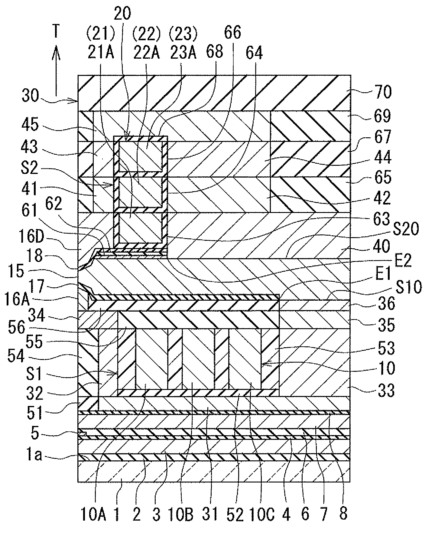
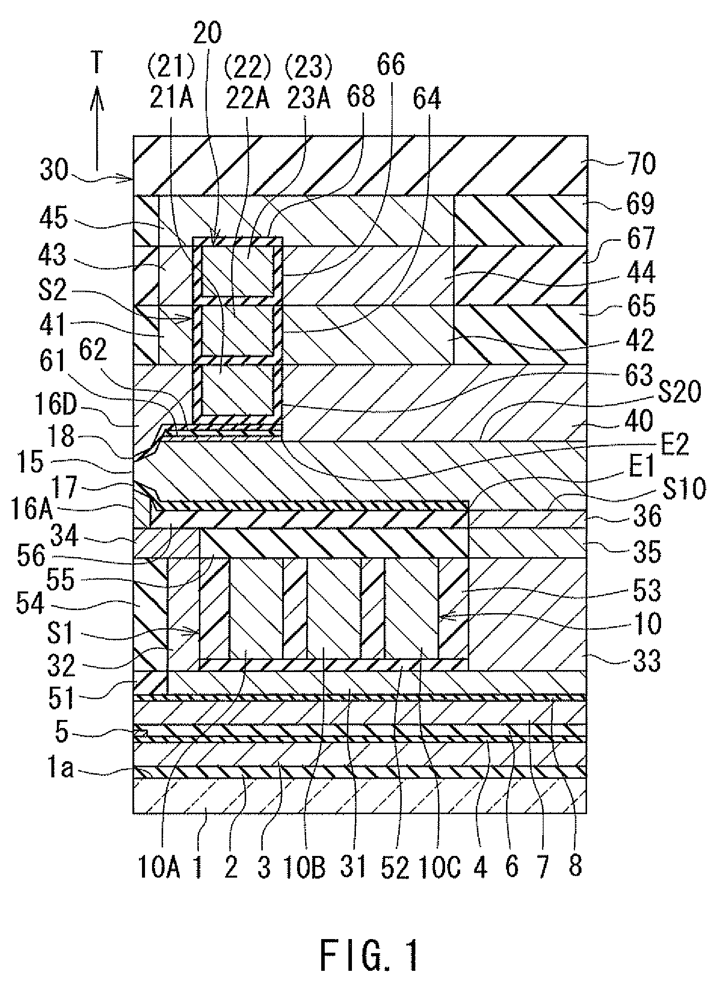
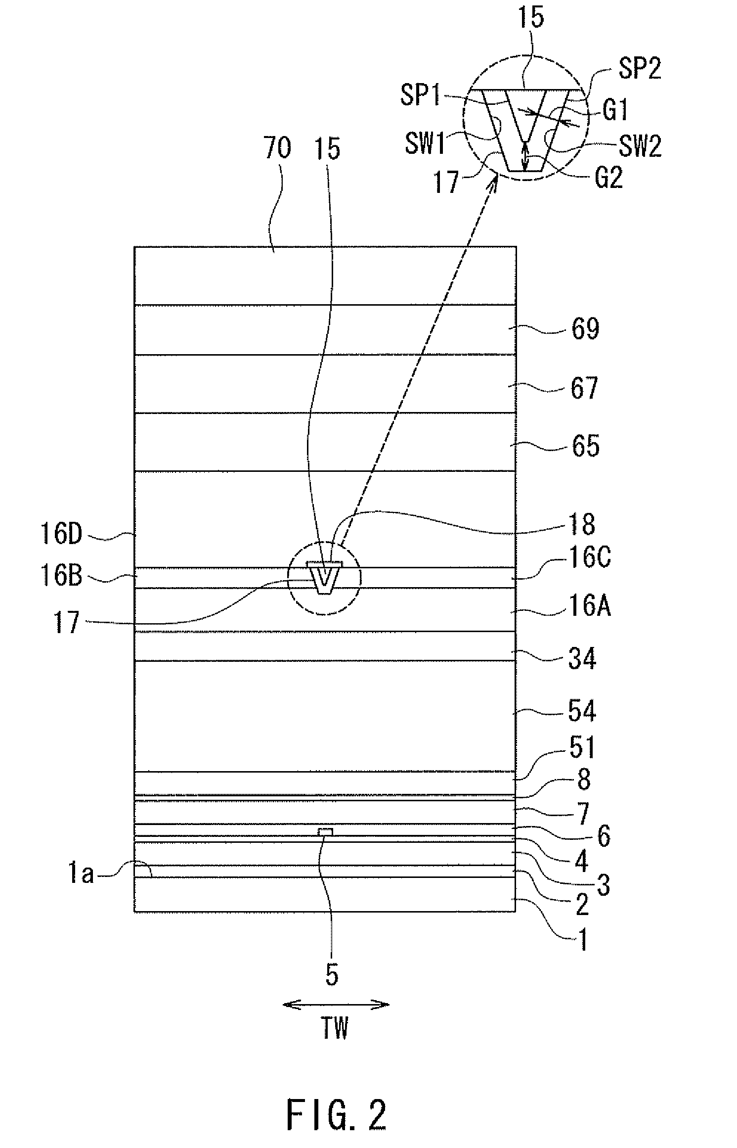
[0046]Embodiments of the present invention will now be described in detail with reference to the drawings. First, reference is made to FIG. 1 to FIG. 6 to describe the configuration of a magnetic head according to a first embodiment of the invention. FIG. 1 is a cross-sectional view of the magnetic head according to the present embodiment. Note that FIG. 1 shows a cross section perpendicular to the medium facing surface and the top surface of the substrate. The arrow with the symbol T in FIG. 1 indicates the direction of travel of the recording medium. FIG. 2 is a front view showing the medium facing surface of the magnetic head according to the present embodiment. FIG. 3 is a plan view showing a first portion of a coil in the magnetic head according to the present embodiment. FIG. 4 is a plan view showing a first layer of a second portion of the coil in the magnetic head according to the present embodiment. FIG. 5 is a plan view showing a second layer of the second portion of the c...

second embodiment

[0127]A magnetic head according to a second embodiment of the invention will now be described with reference to FIG. 9 and FIG. 10. FIG. 9 is a plan view showing a plurality of first coil elements of the coil in the magnetic head according to the present embodiment. FIG. 10 is a plan view showing a plurality of second coil elements of the coil in the magnetic head according to the present embodiment.

[0128]The magnetic head according to the present embodiment is different from the magnetic head according to the first embodiment in the following respects. In the magnetic head according to the present embodiment, the coil is wound approximately three turns around the main pole 15. The coil of the present embodiment has three line-shaped portions 11, 12 and 13 shown in FIG. 9, instead of the first portion 10 of the first embodiment shown in FIG. 3. The coil of the present embodiment further has first to third layers 21, 22 and 23 shaped as shown in FIG. 9, instead of the first to third ...

third embodiment

[0133]A magnetic head according to a third embodiment of the invention will now be described with reference to FIG. 11. FIG. 11 is a cross-sectional view of the magnetic head according to the present embodiment. FIG. 11 shows a cross section perpendicular to the medium facing surface and the top surface of the substrate, or the main cross section, in particular.

[0134]The magnetic head according to the present embodiment is different from the magnetic head according to the first embodiment in the following respects. In the magnetic head according to the present embodiment, each of the magnetic layers 41, 43 and 45 has an end face located in the medium facing surface 30. FIG. 11 shows an example where the coil includes the first portion 10 and the second portion 20 as in the first embodiment. However, the coil of the present embodiment may be configured to be wound helically around the main pole 15 as in the second embodiment.

[0135]The remainder of configuration, function and effects ...


PUM

PropertyMeasurementUnit
thicknessaaaaaaaaaa
thicknessaaaaaaaaaa
heightaaaaaaaaaa

Abstract

A magnetic head includes: a coil; a main pole; a first shield disposed backward of the main pole along a direction of travel of a recording medium; a first return path section connecting the first shield to the main pole; a second shield disposed forward of the main pole along the direction of travel of the recording medium; and a second return path section connecting the second shield to the main pole. An interface between the first return path section and the main pole has an end closest to a medium facing surface, and an interface between the second return path section and the main pole has an end closest to the medium facing surface, the latter being closer to the medium facing surface than the former. The second return path section includes a yoke layer located away from the medium facing surface and in contact with the main pole. The coil includes at least one coil element that passes between the second shield and the yoke layer.

Description

BACKGROUND OF THE INVENTION[0001]1. Field of the Invention[0002]The present invention relates to a magnetic head for perpendicular magnetic recording that is used for writing data on a recording medium by means of a perpendicular magnetic recording system, and more specifically, to a magnetic head for perpendicular magnetic recording that has a main pole and two shields.[0003]2. Description of Related Art[0004]The recording systems of magnetic read / write apparatuses include a longitudinal magnetic recording system wherein signals are magnetized in a direction along the plane of the recording medium (the longitudinal direction) and a perpendicular magnetic recording system wherein signals are magnetized in a direction perpendicular to the plane of the recording medium. It is known that the perpendicular magnetic recording system is harder to be affected by thermal fluctuation of the recording medium and capable of providing higher linear recording density, compared with the longitudi...

Claims


Application Information

Patent Timeline
Patent Type & Authority Patents(United States)
IPC IPC(8): G11B5/127
CPCG11B5/1278G11B5/3116G11B5/3146
Inventor SASAKI, YOSHITAKAITO, HIROYUKISATO, KAZUKIIIJIMA, ATSUSHI
Owner HEADWAY TECH INC
Why Eureka
Try Eureka