Rotary electric shaver

a rotary electric shaver and electric shaver technology, applied in the direction of metal working apparatus, etc., can solve the problems of inability to adjust the shaver, and inability to use the shaver comfortably, so as to reduce the contact pressure, and reduce the effect of contact pressur

Inactive Publication Date: 2012-07-17
IZUMI PROD CO
View PDF38 Cites 14 Cited by
  • Summary
  • Abstract
  • Description
  • Claims
  • Application Information

AI Technical Summary

Benefits of technology

[0010]The present invention has been accomplished under the circumstances as aforementioned, and an object thereof is to provide a rotary electric shaver which reduces the contact pressure applied by an outer cutter and a rim surrounding the outer cutter (hereinafter referred to also as “the cutter circumferential rim” or “outer cutter rim”) to skin thereby to adequately protect the skin, permits a reduced size of a head unit at the top of a main body, minimizes the chances of shaving debris adhering to a pivotal supporting section, allows the cutter circumferential rim to effect smooth pivotable movement for a prolonged time, and permits easy removal of shaving debris.

Problems solved by technology

However, the aforesaid construction provides the outer cutters with a limited movable range relative to the outer cutter frame, thus presenting a problem in that the close contact between the outer cutters and skin is restricted with resultant unsatisfactory shaving feeling or inadequate user-friendliness.
Both shaving apparatuses disclosed in the documents of the prior arts each has a pivotal supporting section provided between the rim and a fixed unit (the outer cutter frame or the upright wall) of the main body surrounding the rim, thus presenting a problem in that the width of the rim in the radial direction is limited or the outer cutter frame of the main body surrounding the rim inevitably becomes large.
In particular, a small width of the rim in the radial direction causes the outer cutter to strongly abut against the skin when the outer cutter is pressed against the skin, thereby a consequent high contact pressure is applied by the outer cutter.
At this time, the outer cutter slightly moves down relative to the rim, however, the movable amount thereof is limited, leading to a high pressure of contact between the outer cutter and the skin.
This may give rise to a problem of easily hurting the skin.
This may lead to unsmooth operation of the pivotal supporting section and may prevent the rim from effecting pivotable movement, resulting in poor shaving feeling.
In addition, there has been a problem in that shaving debris are not easily removed.

Method used


Image

  • Rotary electric shaver
  • Rotary electric shaver
  • Rotary electric shaver

Examples


first embodiment

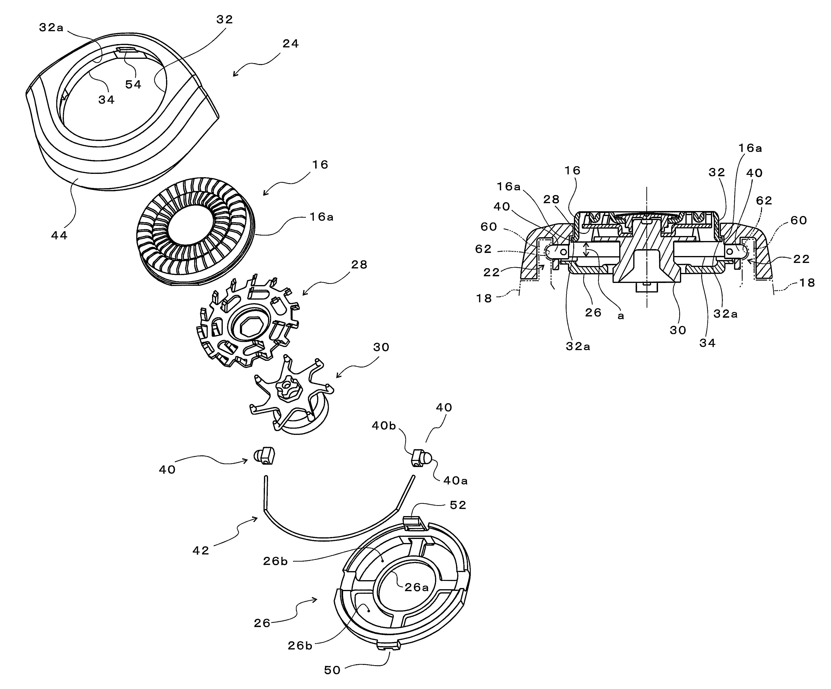
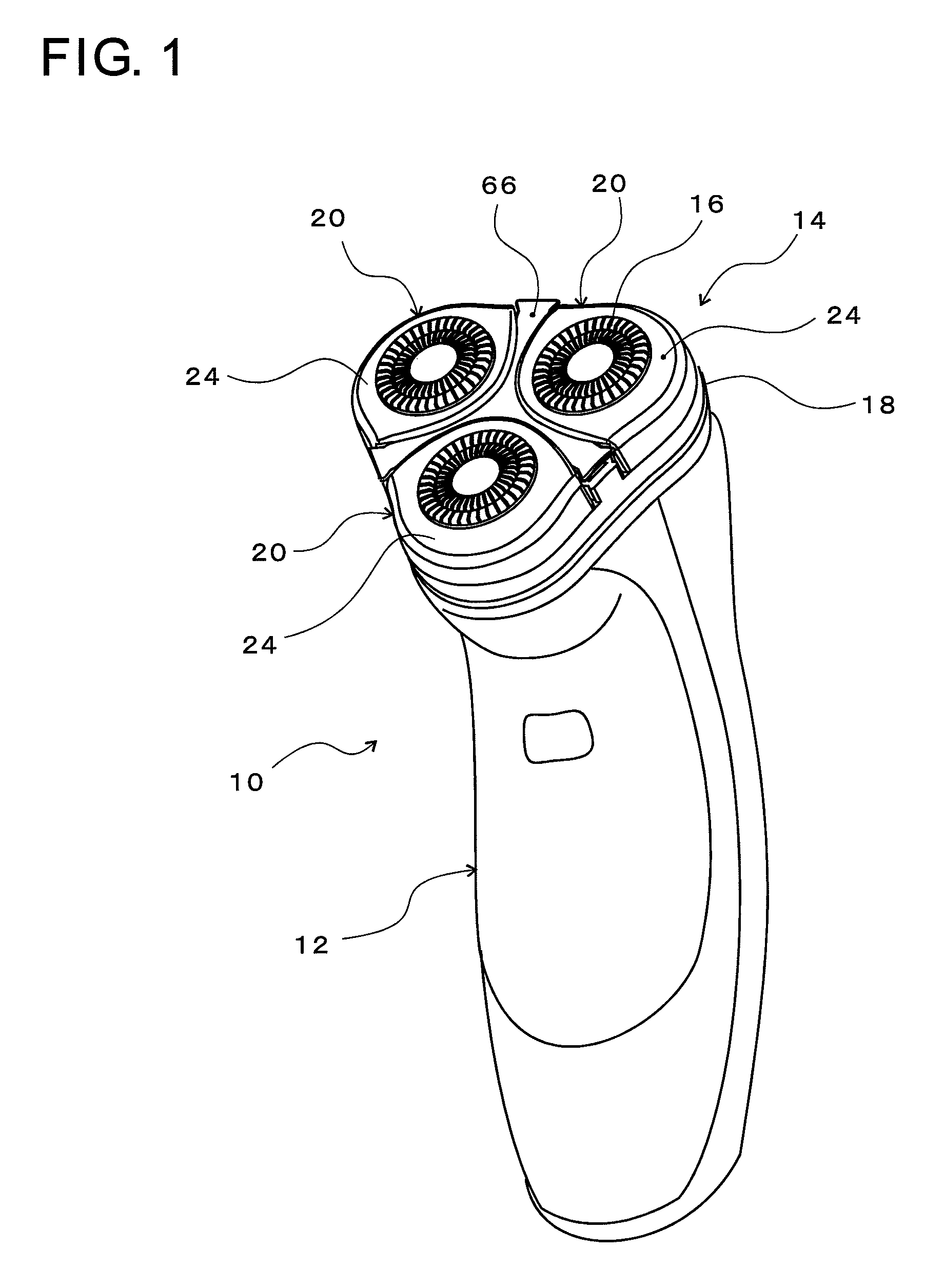
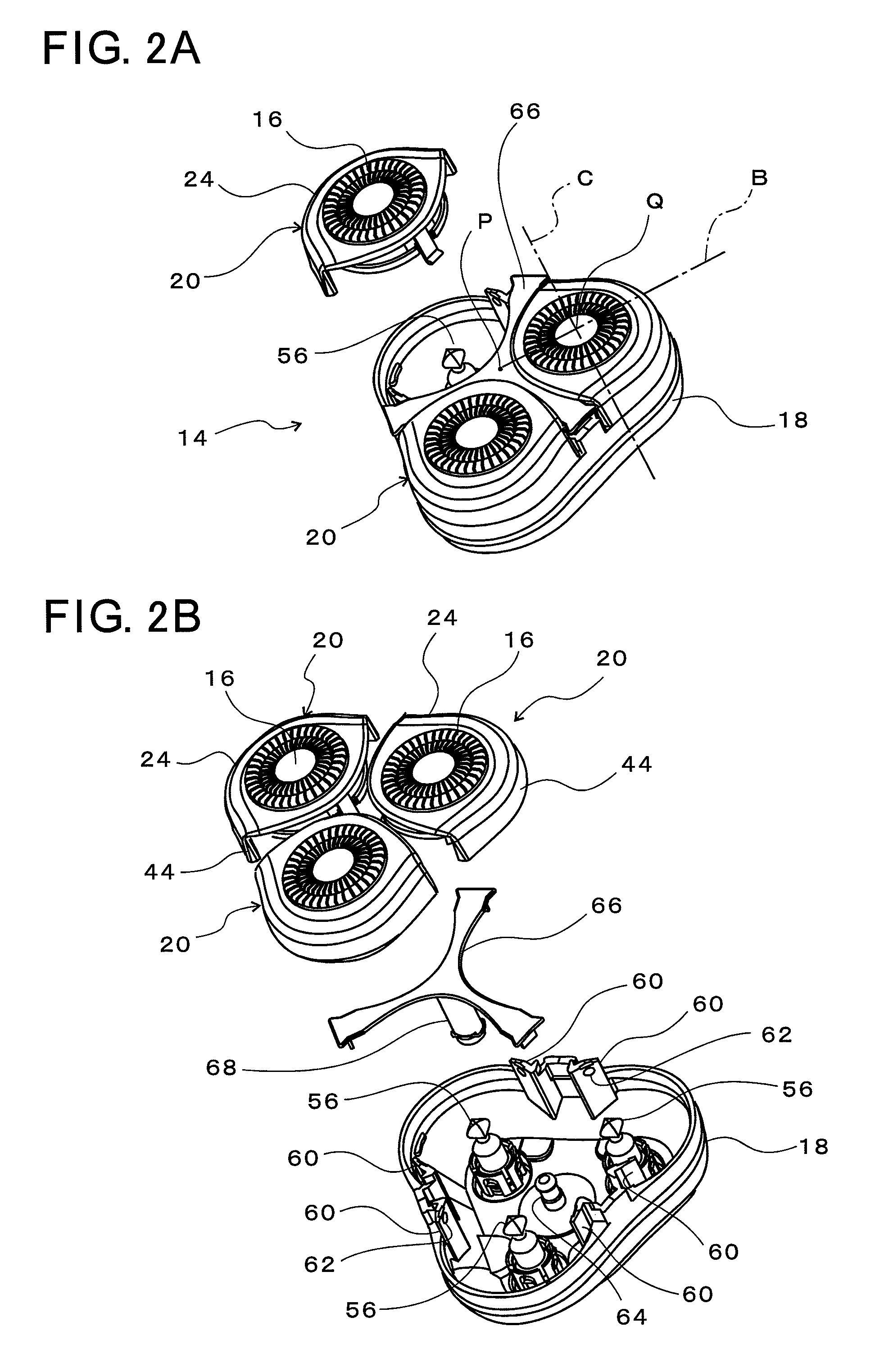
[0031]Referring to FIG. 1, a rotary electric shaver 10 combines a main body 12 and a head unit 14, which is mounted on the upper surface of the main body 12, into one piece. The main body 12 mainly accommodates an electric motor, a battery, and a control circuit (none of them being shown). The head unit 14 has three outer cutters 16 disposed on an equilateral-triangular apexes. Three cutter assemblies 20 are detachably retained on a head bottom plate 18, which provides the upper surface of the main body 12, such that the three cutter assemblies 20 are disposed equidistantly (at 120-degree intervals) relative to a center P of the head unit 14.

[0032]Each of the cutter assemblies 20 is pivotable about a straight line (pivotal axis) C which is orthogonal to a straight line B in a radial direction passing a center P (FIG. 2) of the head unit 14 and which passes a center Q of the outer cutter 16. In other words, each of the three cutter assemblies 20 is independently supported by pivotal ...


PUM


Abstract

The rotary electric shaver comprising; cutter circumferential rims (24), each of which is separately provided for each outer cutter (16) and which holds the outer cutter by surrounding the outer periphery of the outer cutter, and pivotal supporting sections (22) which pivotably and removably hold the cutter circumferential rim on a pivotal axis (C) passing the center (Q) of the outer cutter. The upper surface of the cutter circumferential rim is extended out over the pivotal supporting sections, thus increasing the width of the upper surface of the cutter circumferential rim.

Description

BACKGROUND OF THE INVENTION[0001]1. Field of the Invention[0002]The present invention relates to a rotary electric shaver which rotatively drives inner cutters, which are in resilient contact with inner bottom surfaces of circular outer cutters.[0003]2. Description of the Related Art[0004]There has been known a so-called rotary electric shaver which has circular or disk-shaped outer cutters and inner cutter rotating on the inner side of the outer cutters so that beard hair entering the hair introduction slits formed in the outer cutters is cut by the rotating inner cutters. As this type of electric shaver, there has been known in which outer cutter installing holes are formed in an outer cutter frame secured to a shaver main body and circular outer cutters are supported in the outer cutter installing holes such that the outer cutters are slightly movable in a vertical direction and slightly inclinable with respect to the outer cutter frame.[0005]However, the aforesaid construction p...

Claims


Application Information

Patent Timeline
Patent Type & Authority Patents(United States)
IPC IPC(8): B26B19/04B26B19/14
CPCB26B19/145B26B19/14
Inventor SHIMIZU, TETSUHIKO
Owner IZUMI PROD CO
Why Eureka
Try Eureka