Low power digital phase lock loop circuit
a low-power, phase lock loop technology, applied in the direction of phase difference detection of angle, automatic control, electrical equipment, etc., can solve problems such as noise, and achieve the effect of increasing the overall power usage of conventional dpll circuit 100 and consuming a lot of power
- Summary
- Abstract
- Description
- Claims
- Application Information
AI Technical Summary
Problems solved by technology
Method used
Image
Examples
Embodiment Construction
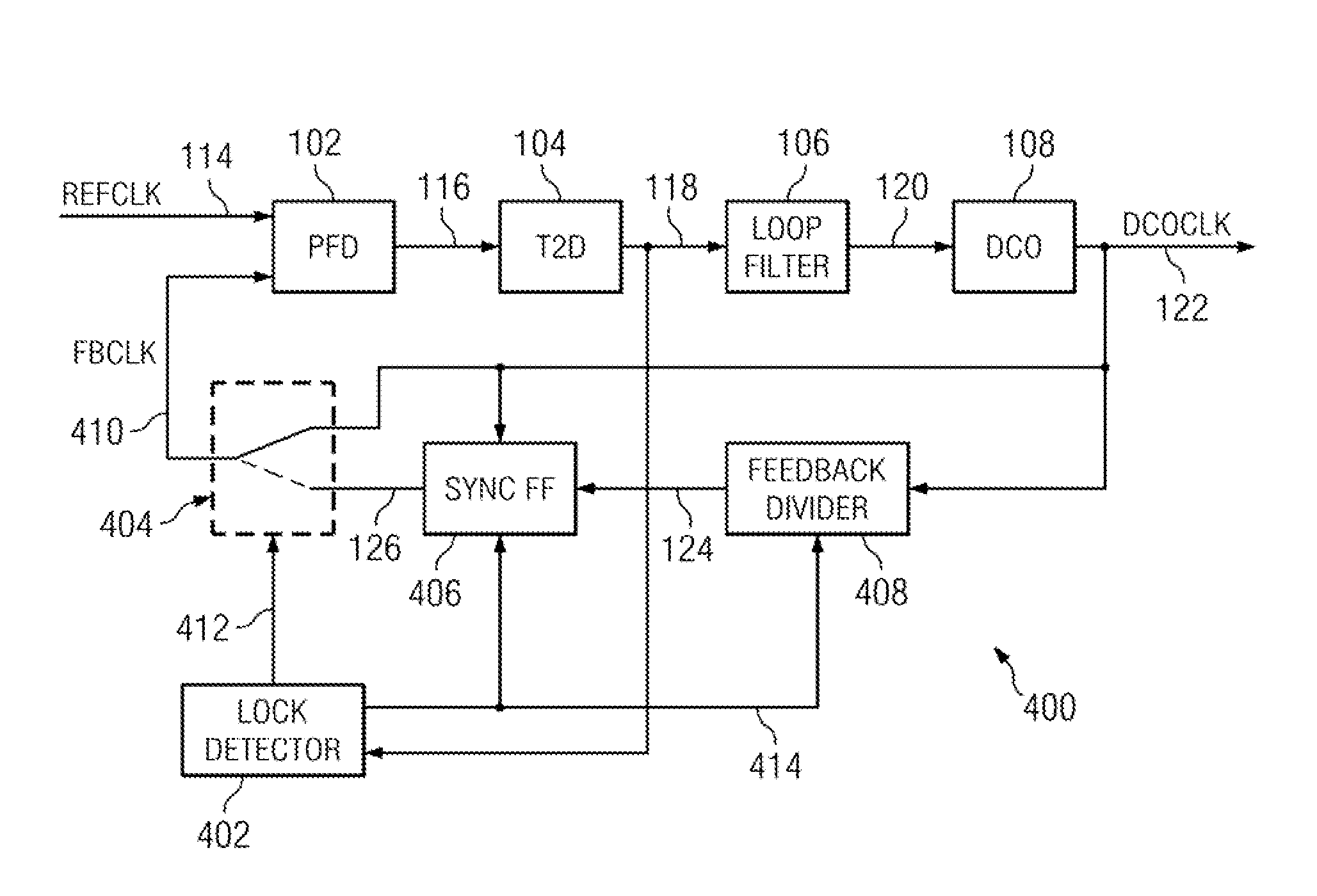
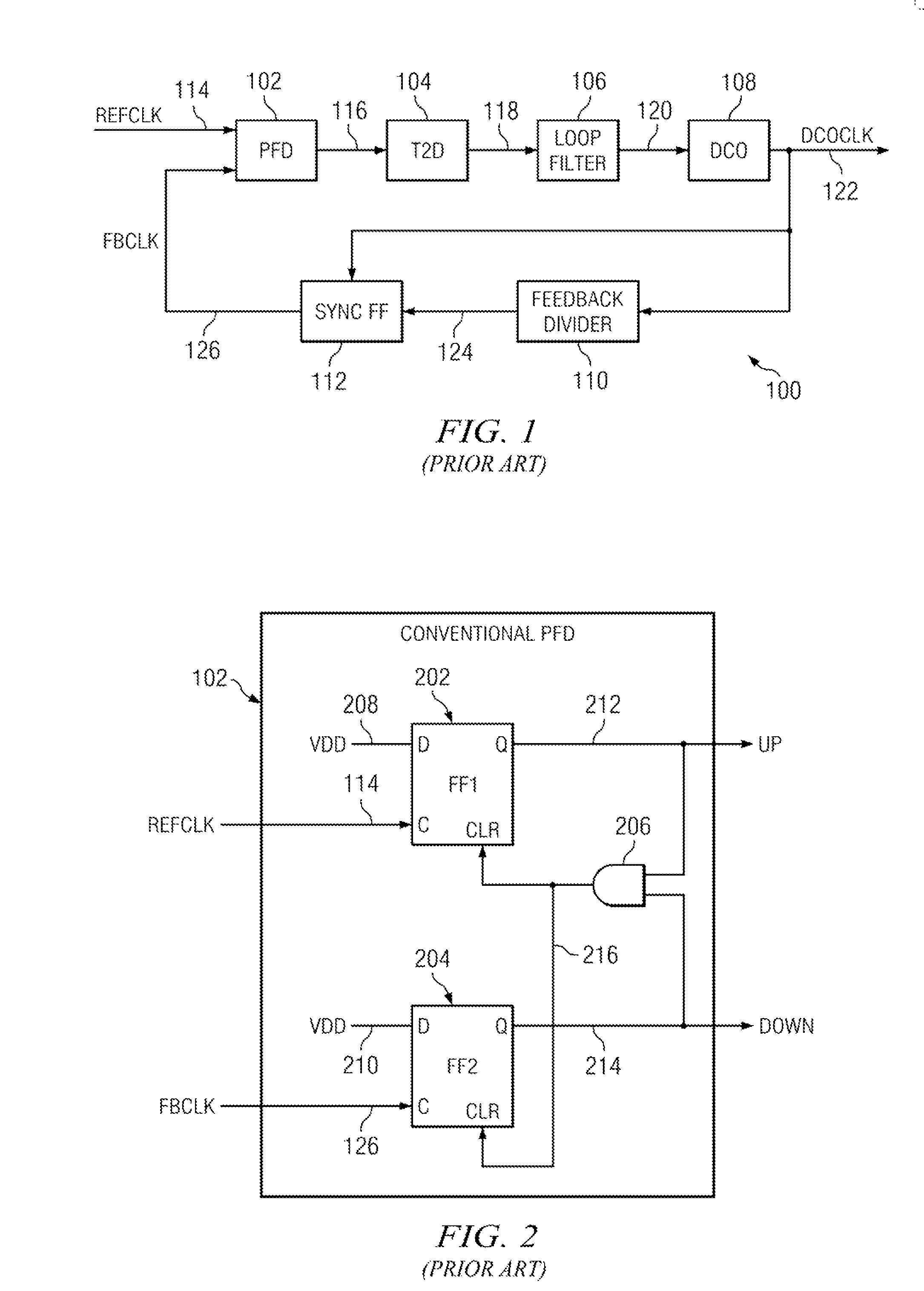
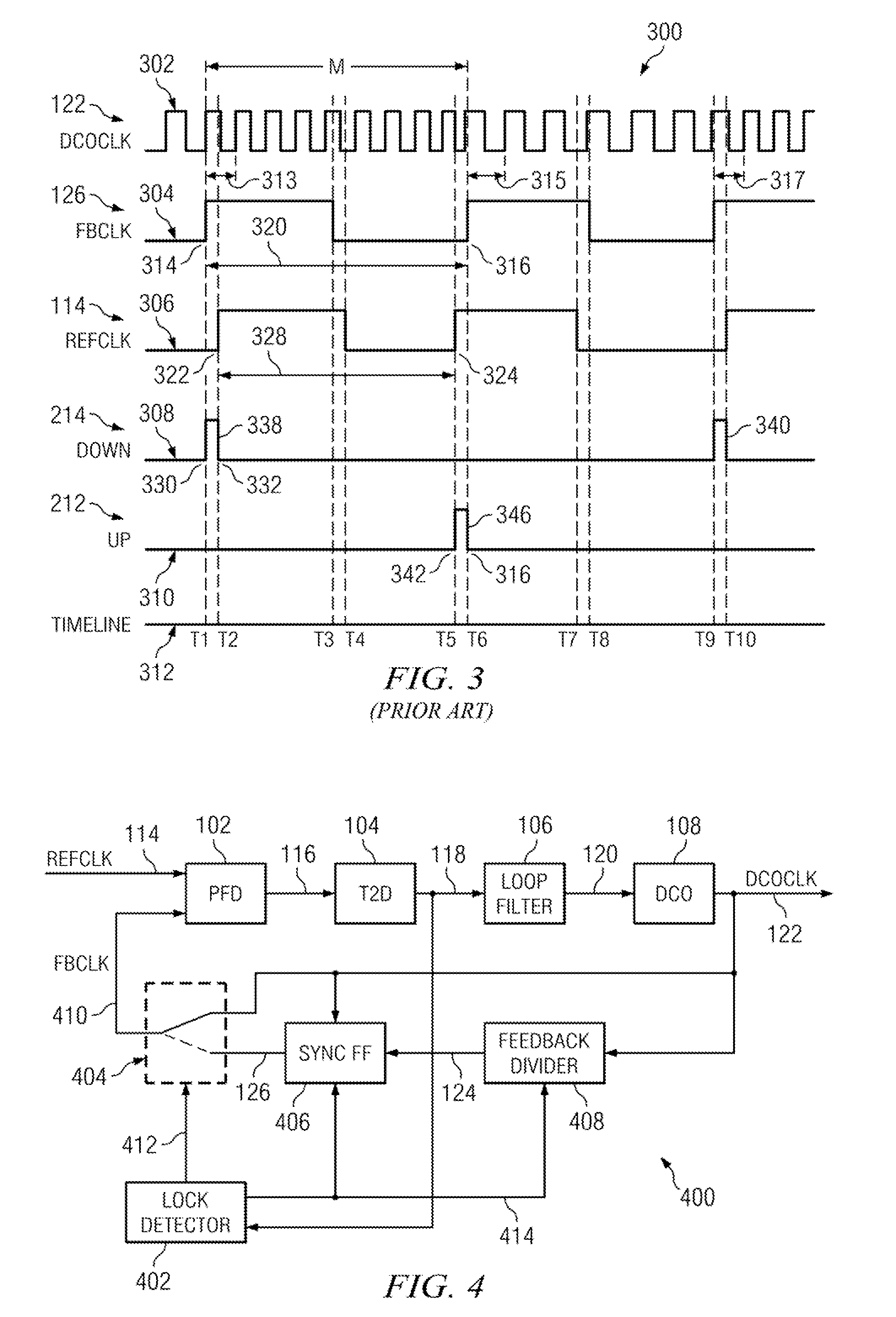
[0047]In accordance with an aspect of the present invention, a DPLL circuit initially functions like a conventional DPLL circuit by correcting the phase error between a reference clock signal and a feedback clock signal until both clock signals are aligned and the DPLL is locked. At that point, under certain conditions, in accordance with aspects of the present invention, the phase error can be derived from a phase comparison between an edge in the reference clock signal and the next closest edge in the oscillator clock signal rather than an edge in the feedback clock signal. In short, the feedback divider and the sync FF are bypassed, whereas the PFD compares the reference clock signal with the oscillator clock signal.
[0048]Aspects of the present invention may provide two distinct advantages over conventional DPLL circuits. First, if the phase jitter of DPLL is sufficiently small (which it is in many applications) the feedback divider can be disabled once initial frequency lock is ...
PUM
 Abstract
Description
Claims
Application Information
 - R&D
- Intellectual Property
- Life Sciences
- Materials
- Tech Scout
- Unparalleled Data Quality
- Higher Quality Content
- 60% Fewer Hallucinations
Browse by: Latest US Patents, China's latest patents, Technical Efficacy Thesaurus, Application Domain, Technology Topic, Popular Technical Reports.
© 2025 PatSnap. All rights reserved.Legal|Privacy policy|Modern Slavery Act Transparency Statement|Sitemap|About US| Contact US: help@patsnap.com


