
X-ray tomographic inspection systems for the identification of specific target items

a tomographic inspection and target item technology, applied in the field of xray scanning, can solve the problem that the swept beam scanner is not compatible with the conveyor system, and achieve the effect of improving the accuracy of the swept beam scanner

Active Publication Date: 2012-07-17
RAPISCAN SYST INC (US)
View PDF293 Cites 31 Cited by
  • Summary
  • Abstract
  • Description
  • Claims
  • Application Information

AI Technical Summary

Problems solved by technology

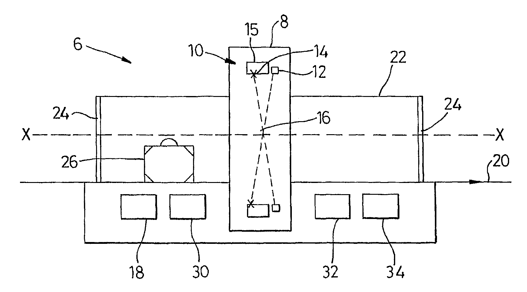
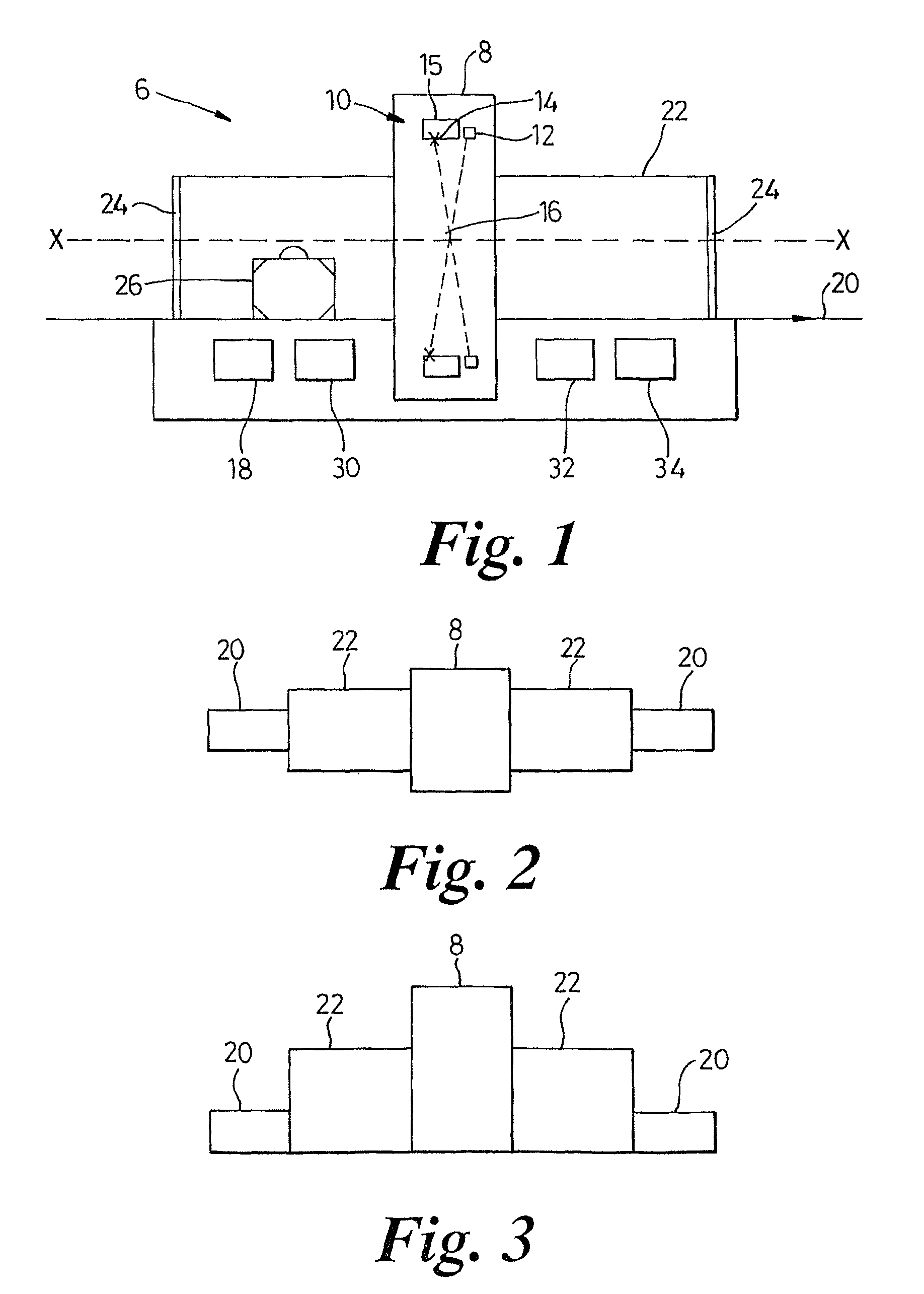
However, because the electron source lies on the axis of rotation, such swept beam scanners are not compatible with conveyor systems which themselves pass close, and parallel, to the axis of rotation.

Method used


Image

  • X-ray tomographic inspection systems for the identification of specific target items
  • X-ray tomographic inspection systems for the identification of specific target items
  • X-ray tomographic inspection systems for the identification of specific target items

Examples


second embodiment

[0086]Referring to FIG. 7 the invention comprises a redundant system in which two RTT scanning systems 70, 72 are located in series on the same conveyor 74 such that if one system were to be taken out of service, then the other could continue to scan baggage. In either case, the conveyor belt 74 would continue to run through both scanning systems 70, 72 at standard operating belt speed.

third embodiment

[0087]Referring to FIG. 8a in a third embodiment there is provided a more complex redundant system in which two RTT systems 82, 84 are operated in parallel. A first main incoming conveyor 86 brings all items to be sorted to a first sorting device 88 which can transfer items onto either one of two further conveyors 90, 92. Each of these two conveyors 90, 92 passes through a respective one of the scanning systems 82, 84, which will scan the items and enable a decision to be made as to whether to clear the item or not. A further sorting device 94, 96 is provided on each of the two conveyors 90, 92 which is arranged to sort the baggage onto a common ‘green channel’ conveyor 98 for onward transportation, or a ‘red channel’ conveyor 100 if it is not cleared, where it can undergo further investigation. In this configuration, it is possible to run the input conveyor 86, and the ‘green channel’ conveyor at a higher speed than the RTT conveyor speed, typically up to twice the speed. For examp...


PUM

PropertyMeasurementUnit
densityaaaaaaaaaa
angleaaaaaaaaaa
speedaaaaaaaaaa

Abstract

The present specification discloses an X-ray scanning system with a non-rotating X-ray scanner that generates scanning data defining a tomographic X-ray image of the object and a processor executing programmatic instructions where the executing processor analyzes the scanning data to extract at least one parameter of the tomographic X-ray image and where the processor is configured to determine if the object comprises a liquid, sharp object, narcotic, currency, nuclear materials, cigarettes or fire-arms.

Description

CROSS-REFERENCE TO RELATED APPLICATIONS[0001]The present application relies on U.S. Patent Provisional Application No. 61 / 181,068 filed on May 26, 2009, for priority.[0002]The present application is also a continuation-in-part of U.S. patent application Ser. No. 12 / 485,897, filed on Jun. 16, 2009, now abandoned which is a continuation of U.S. patent application Ser. No. 10 / 554,656, filed on Mar. 29, 2007, and now issued U.S. Pat. No. 7,564,939, which is a 371 national stage application of PCT / GB04 / 01729, filed on Apr. 23, 2004 and which, in turn, relies on Great Britain Application No. 0309387.9, filed on Apr. 25, 2003, for priority.[0003]The present application is also a continuation-in-part of U.S. patent application Ser. No. 12 / 371,853, filed on Feb. 16, 2009, now U.S. Pat. No. 7,903,789 which is a continuation of U.S. patent application Ser. No. 10 / 554,975, filed on Aug. 2, 2006, and now issued U.S. Pat. No. 7,512,215, which is a 371 national stage application of PCT / GB2004 / 0174...

Claims


Application Information

Patent Timeline
Patent Type & Authority Patents(United States)
IPC IPC(8): G01N23/04
CPCG01N23/046H01J35/04H01J35/24H01J35/045G01N2223/639G01N2223/419H01J2235/068A61B6/027
Inventor MORTON, EDWARD JAMES
Owner RAPISCAN SYST INC (US)
Learn More