Impregnated bit with increased binder percentage

a technology of diamonds and impregnated bits, applied in drill bits, earthwork drilling and mining, cutting machines, etc., can solve the problems of wear of matrix loss of worn abrasives, etc., and achieve the effect of increasing the soft binder percentage, more diamond grit, and replacing faster

Inactive Publication Date: 2012-07-24
BAKER HUGHES INC
View PDF24 Cites 13 Cited by
  • Summary
  • Abstract
  • Description
  • Claims
  • Application Information

AI Technical Summary

Benefits of technology

[0027]Control of the carbide volume in the matrix in an impregnated bit is accomplished by coating the hard particles in the matrix to space them further apart to increase the soft binder percentage in a controllable manner. The softer binder due to lower volume content of hard particles allows more rapid matrix wear in the softer formations to allow more diamond grit to cut better before getting flat spots and to be replaced faster with additional diamond grit further into the matrix as the higher content of the softer binder and the softer coating on the hard particles in the matrix promotes more effective cutting with more frequent emergence of diamond grit on the bit face as cutting progresses.

Problems solved by technology

As a conventional impregnated drag bit drills, the matrix wears to expose the abrasive particles, the abrasive particles also wear, and worn abrasive particles may be lost and new abrasive particles, which were previously surrounded by matrix material, may be exposed.
The slower the wear rate, the less new diamond is exposed to the formation, and the lower the projection or protrusion of the diamond grit, resulting in a lower rate of penetration, shorter bit life as the grit glazes over and develops a large wear flat, and loses its ability to cut effectively.
It is difficult to lower the hard particle concentration, and raise the binder portion in a controlled manor due to the packing of the carbide particles during handling in the mold in manufacturing, and by segregation of the nickel powders when they are added.

Method used


Image

  • Impregnated bit with increased binder percentage
  • Impregnated bit with increased binder percentage
  • Impregnated bit with increased binder percentage

Examples


Embodiment Construction

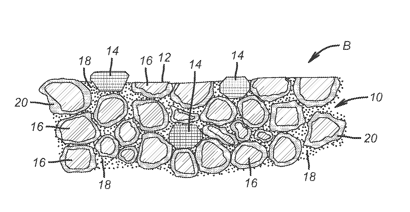
[0031]FIG. 2 simulates a photomicrograph to illustrate the present invention by showing a highly magnified portion of the body 10 of an impregnated bit matrix B where the top of the FIG. 2 represents the bit face 12. Diamond grit 14 extends in varying degrees through the face 12 before cutting begins and throughout the matrix B. The principle of operation is that the diamond grit 14 on the face 12 starts the cutting of the formation and wears as a result along with the surrounding matrix that holds the diamond grit 14 in position. The surrounding matrix B wears as well and at some point the diamond grit 14 is knocked out of the matrix B at the approximate time that additional grit 14 becomes exposed to maintain the optimal rate of penetration.

[0032]In certain soft formations the currently available matrix B formulations are too abrasive wear resistant leading to overly long exposure of a given number of diamond grit particles 14 until such grit gets flat spots and loses its ability ...


PUM

PropertyMeasurementUnit
thickaaaaaaaaaa
thicknessaaaaaaaaaa
thicknessaaaaaaaaaa

Abstract

Control of the carbide volume in the matrix in an impregnated bit is accomplished by coating the hard particles in the matrix to space them further apart to increase the soft binder percentage in a controllable manner. The softer binder due to lower volume content of hard particles allows more rapid matrix wear in the softer formations to allow more diamond grit to cut better before getting flat spots and to be replaced faster with additional diamond grit further into the matrix as the higher content of the softer binder and the softer coating on the hard particles in the matrix promotes more effective cutting with more frequent emergence of diamond grit on the bit face as cutting progresses.

Description

FIELD OF THE INVENTION[0001]The field of the invention is diamond impregnated bits and more particularly the manner in which the matrix durability is altered to improve rate of penetration and bit life.BACKGROUND OF THE INVENTION[0002]So-called “impregnated” drag bits have been used conventionally for drilling rock formations that are hard, abrasive, or both. More particularly, conventional earth boring drag bits with diamond-impregnated cutting structures, commonly termed “segments,” or, alternatively, discrete diamond-impregnated cutting structures have been employed to bore through very hard and abrasive formations, such as basalt, dolomite, and hard sandstone. These conventional impregnated drag bits typically employ a cutting face comprising a diamond impregnated material, which refers to an abrasive particle or material, such as natural or synthetic diamond grit, uniformly dispersed within a matrix of surrounding material. As a conventional impregnated drag bit drills, the mat...

Claims


Application Information

Patent Timeline
Patent Type & Authority Patents(United States)
IPC IPC(8): E21B10/36
CPCE21B10/54
Inventor SCOTT, DAN E.
Owner BAKER HUGHES INC
Why Eureka
Try Eureka