Adjustable corner clamping apparatus

a clamping apparatus and adjustable technology, applied in the field of clamping apparatus, can solve the problems of limited capacity of hahn apparatus for clamping wide frame strips, inability to generate longitudinal axis compression of framing strips or corner pieces, complex design of hahn apparatus, etc., and achieve the effect of convenient manufacturing of clamping apparatus, adequate compression, and economical us

Inactive Publication Date: 2012-07-24
HUGHEY CHRISTOPHER N
View PDF41 Cites 31 Cited by
  • Summary
  • Abstract
  • Description
  • Claims
  • Application Information

AI Technical Summary

Benefits of technology

[0010]My clamping apparatus optimally addresses several critical issues typical to corner clamping. These issues include the need (1) to adjust for different corner piece lengths, (2) to adjust for different corner piece widths, (3) to generate adequate compression between the mated corner pieces, (4) to compensate for variations in the miter seam, and (5) to provide an economical and easy to manufacture clamping apparatus.

Problems solved by technology

However, the Hahn apparatus is not capable of generating longitudinal axis compression of framing strips or corner pieces.
Further, the arrangement of the clamping screws in the Hahn apparatus limits its capability for clamping wide frame strips.
Finally, the Hahn apparatus is a complex design requiring customized metal machining.
However, the apparatus is otherwise subject to the same limitations as the prior Hahn device.
However, the Sjuts et al reference is limited in the width of material it will clamp, and does not readily allow for adjusting the miter seam.

Method used


Image

  • Adjustable corner clamping apparatus
  • Adjustable corner clamping apparatus
  • Adjustable corner clamping apparatus

Examples


Embodiment Construction

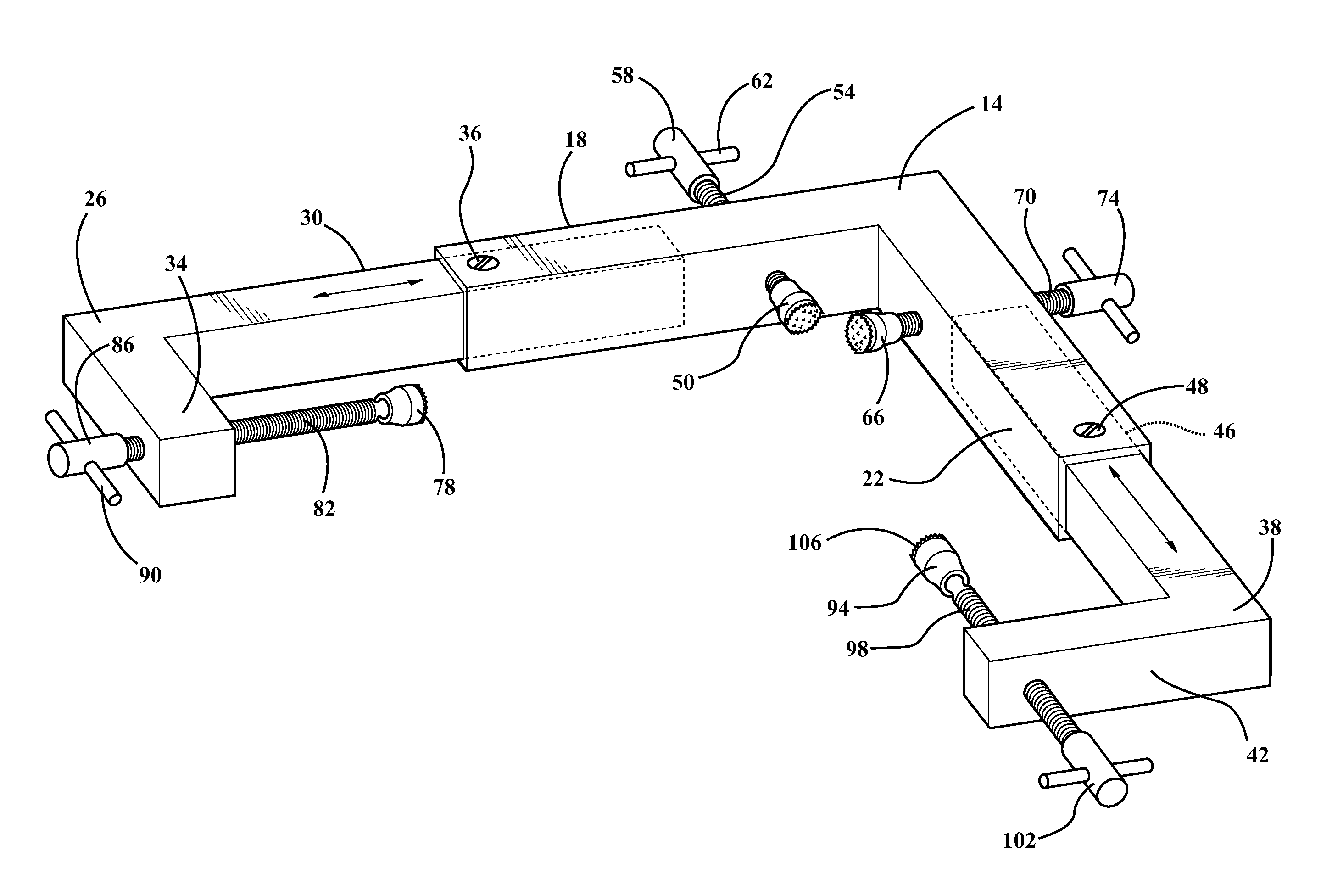
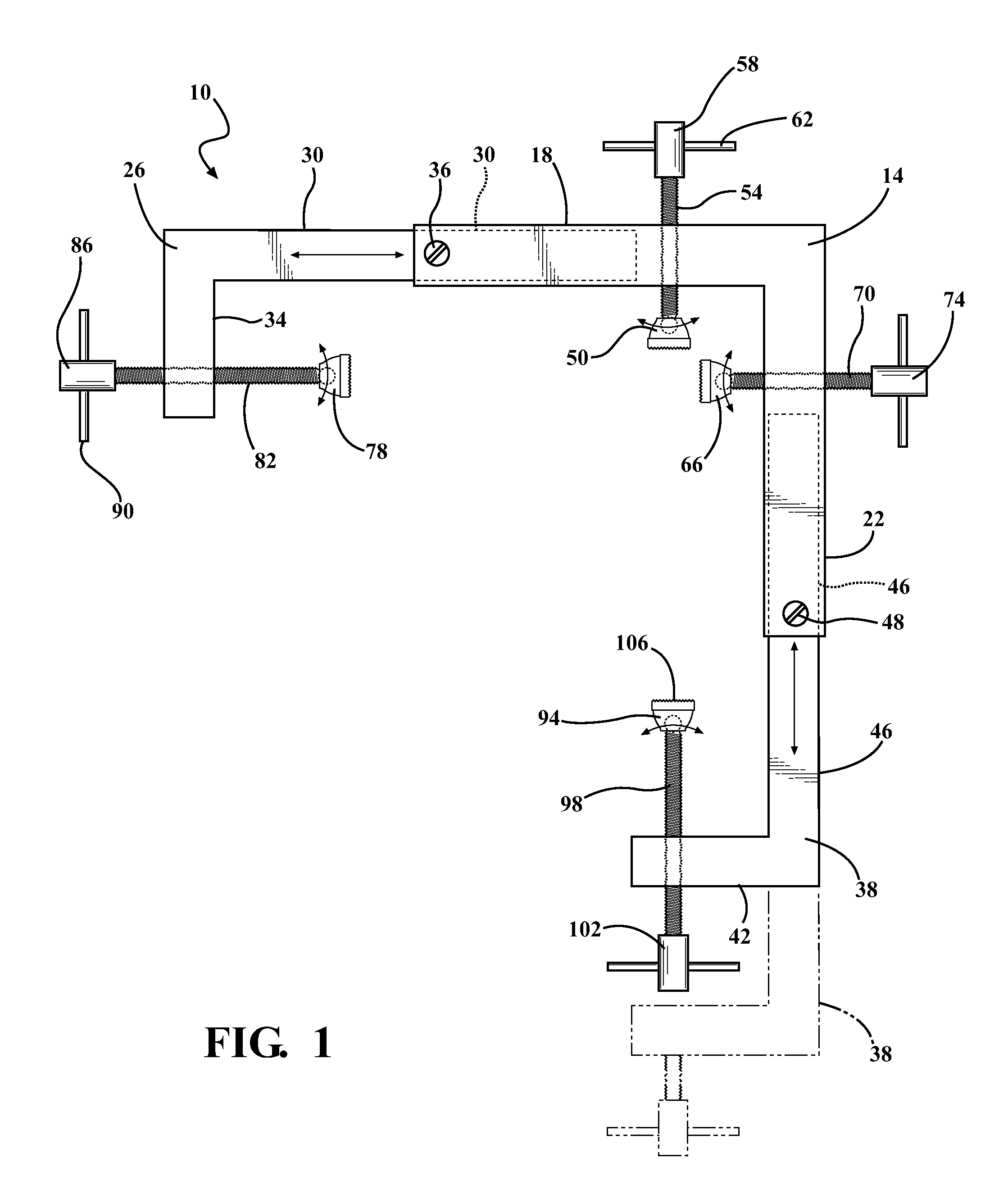
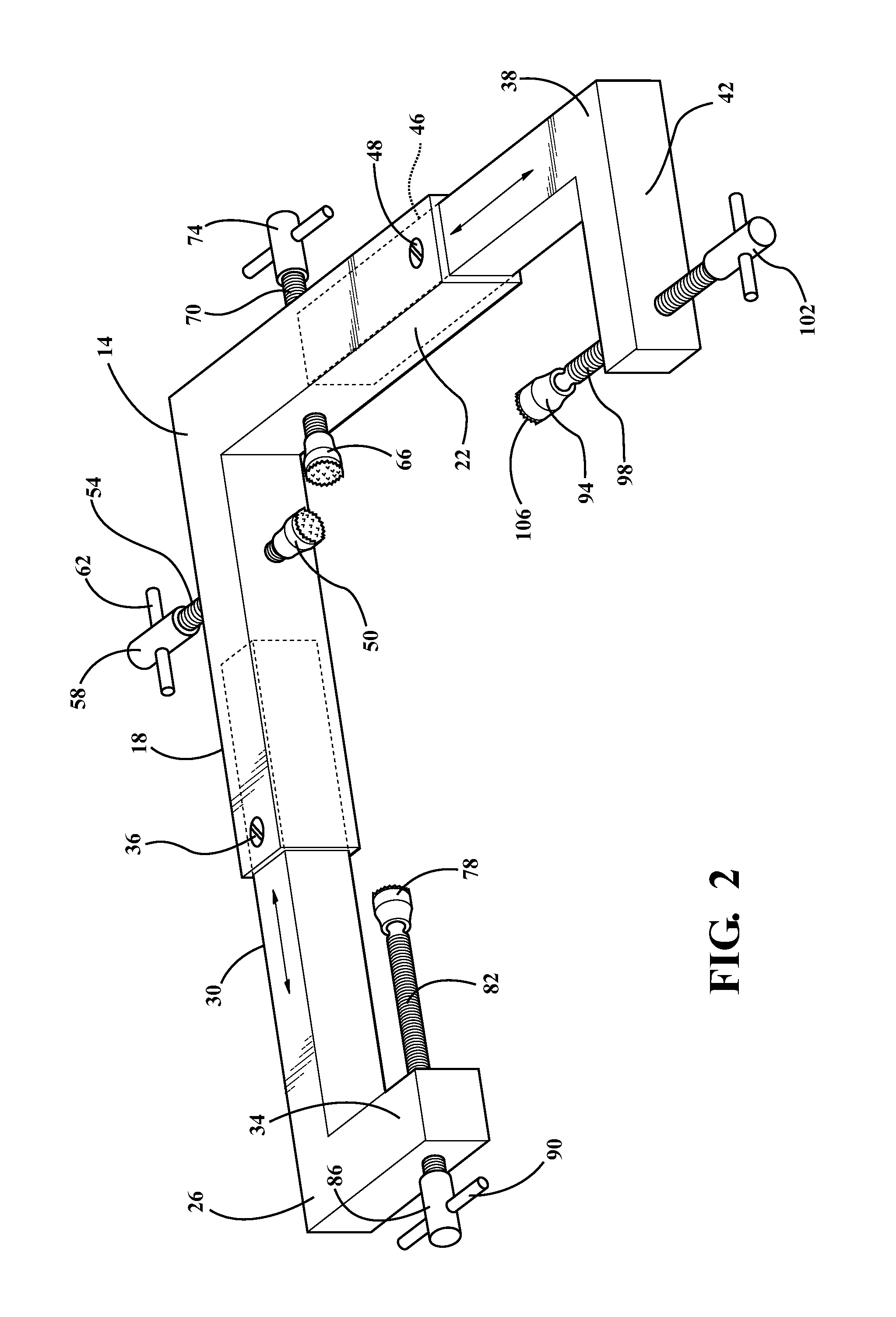
[0017]Referring to FIGS. 1 through 4, a corner clamping apparatus is shown in exemplary form in order to teach how to make and use the claimed invention.

[0018]In FIG. 1, a corner clamping apparatus 10 includes a first rigid L support 14, a second rigid L support 26, a third rigid L support 38, a first clamping foot 50, a second clamping foot 66, a third clamping foot 78, and a fourth clamping foot 94. The rigid L supports 14, 26, and 38 are so named for their general “L” shapes. The first rigid L support 14 has a first leg 18 and a second leg 22. The second rigid L support 26 also has a first leg 30 and a second leg 34.

[0019]The first leg 18 of the first rigid L support 14 and the first leg 30 of the second rigid L support 26 are slidingly coupled together. For example, the rigid L supports may be fabricated from square steel tubing. In the illustrated embodiment, the first rigid L support 14 is fabricated tubing stock of somewhat larger cross section than the second rigid L support...


PUM

PropertyMeasurementUnit
distanceaaaaaaaaaa
widthaaaaaaaaaa
compression forceaaaaaaaaaa

Abstract

A corner clamping apparatus capable of adjustably clamping two joined, mitered corner pieces to form a 90-degree corner with a single clamp. The clamping apparatus includes three rigid L-shaped supports, adjustably mounted relative to one another to accommodate differently sized corner pieces and / or variations in the corner pieces or their mitered edges. Four adjustable clamping feet retained in the rigid L serve to adjust the corner pieces to produce an exact miter joint or seam, and to hold the adjusted corner pieces until they can be more permanently joined.

Description

RELATED APPLICATIONS / PRIORITY BENEFIT CLAIM[0001]This application claims the benefit of U.S. Provisional Application No. 61 / 209,184 filed Mar. 4, 2009 by the same inventor (Hughey), the entirety of which provisional application is incorporated herein by reference.FIELD[0002]The subject matter of the present application is in the field of clamping apparatus for use in producing corners from mating corner pieces with mitered mating edges, by securely retaining the corner pieces in a corner arrangement.BACKGROUND[0003]Devices relating to frame and corner clamps and miters are known. U.S. Pat. No. 4,056,030 to Hahn is directed to a combination miter box, corner clamp, and measuring gauge based on a machined metal, V-shaped structure. However, the Hahn apparatus is not capable of generating longitudinal axis compression of framing strips or corner pieces. Further, the arrangement of the clamping screws in the Hahn apparatus limits its capability for clamping wide frame strips. Finally, t...

Claims


Application Information

Patent Timeline
Patent Type & Authority Patents(United States)
IPC IPC(8): G11B3/00G11B19/24G11B7/26H04B1/20G11B3/70G11B5/84B25B13/46B25B1/00
CPCB25B5/003B25B5/006B25B5/10B25B5/142
Inventor HUGHEY, CHRISTOPHER N.
Owner HUGHEY CHRISTOPHER N
Why Eureka
Try Eureka