Method and apparatus for heating solutions within intravenous lines to desired temperatures during infusion

a technology of heating solution and intravenous line, which is applied in the field of devices for warming intravenous solution, can solve the problems of limiting device heating, increasing system complexity, and serious injury to the patient, and achieves the effect of enhancing thermal transfer and sufficient residence tim

Active Publication Date: 2012-07-24
MEDICAL SOLUTIONS INC
View PDF393 Cites 39 Cited by
  • Summary
  • Abstract
  • Description
  • Claims
  • Application Information

AI Technical Summary

Benefits of technology

[0015]Still another object of the present invention is to configure an IV tubing cassette or cartridge to occupy a minimal amount of warming device housing space, while providing sufficient residence time for fluid to be heated to a desired temperature within the device.
[0016]A further object of the present invention is to thermally treat a warming device IV tubing cassette or cartridge containing fluid, while enabling viewing of the fluid within the device.
[0017]Yet another object of the present invention is to heat IV solution with a warming device employing an IV cassette or cartridge including tubing arranged to form concentric passages that alternately direct IV solution flow in opposing directions to enhance thermal transfer between the passages during solution warming.
[0019]According to the present invention, an IV line temperature controlled warming device includes a housing and a fluid cassette or cartridge that receives fluid from an IV line and includes intravenous line tubing arranged in a preformed configuration to enable the IV line fluid to flow therethrough. The preformed configuration includes tubing sections arranged in generally circular and concentric portions and a central serpentine tubing section that includes a generally ‘S’-shaped configuration. The serpentine section basically reverses fluid flow and facilitates flow in opposing directions within adjacent tubing sections. The fluid cassette is retained within the device on a base plate partially disposed within a device housing interior, while a housing cover is selectively opened and closed to permit access to the base plate. The base plate includes a heater plate disposed thereon, while the cover and heater plate each include heating elements to apply heat to opposing surfaces of the tubing cassette. The heating elements are controlled by a controller in response to measured temperatures of the heater plate and fluid. In addition, the device includes various safeguards that ensure device operation during appropriate conditions (e.g., appropriate temperatures, proper placement of a compatible cassette within the device, etc.).

Problems solved by technology

nt. Thus, the fluid may incur certain undesirable conditions within the devices (e.g., contamination, air bubbles, etc.) that are beyond the view of, and may be undetected by, an operator, thereby risking serious injury to a patie
ture. As a result, the devices may need to further employ flow sensors to measure and account for changes in fluid flow in order to ensure maintenance of proper fluid temperature, thereby increasing system complexity and
costs. Moreover, the overlapping passageways tend to confine thermal energy that may otherwise be distributed to heat the fluid, thereby limiting the device heating pot
tubing. However, this device employs infrared radiation to thermally treat the fluid, thereby involving special safety measures and requiring additional components to isolate the radiation from the
patient. In addition, the above-described systems of the related art include heat exchangers or fluid flow paths including inlets separated from fluid outlets, thereby tending to increase complexity of connections and installation for use with an infusion

Method used


Image

  • Method and apparatus for heating solutions within intravenous lines to desired temperatures during infusion
  • Method and apparatus for heating solutions within intravenous lines to desired temperatures during infusion
  • Method and apparatus for heating solutions within intravenous lines to desired temperatures during infusion

Examples


Embodiment Construction

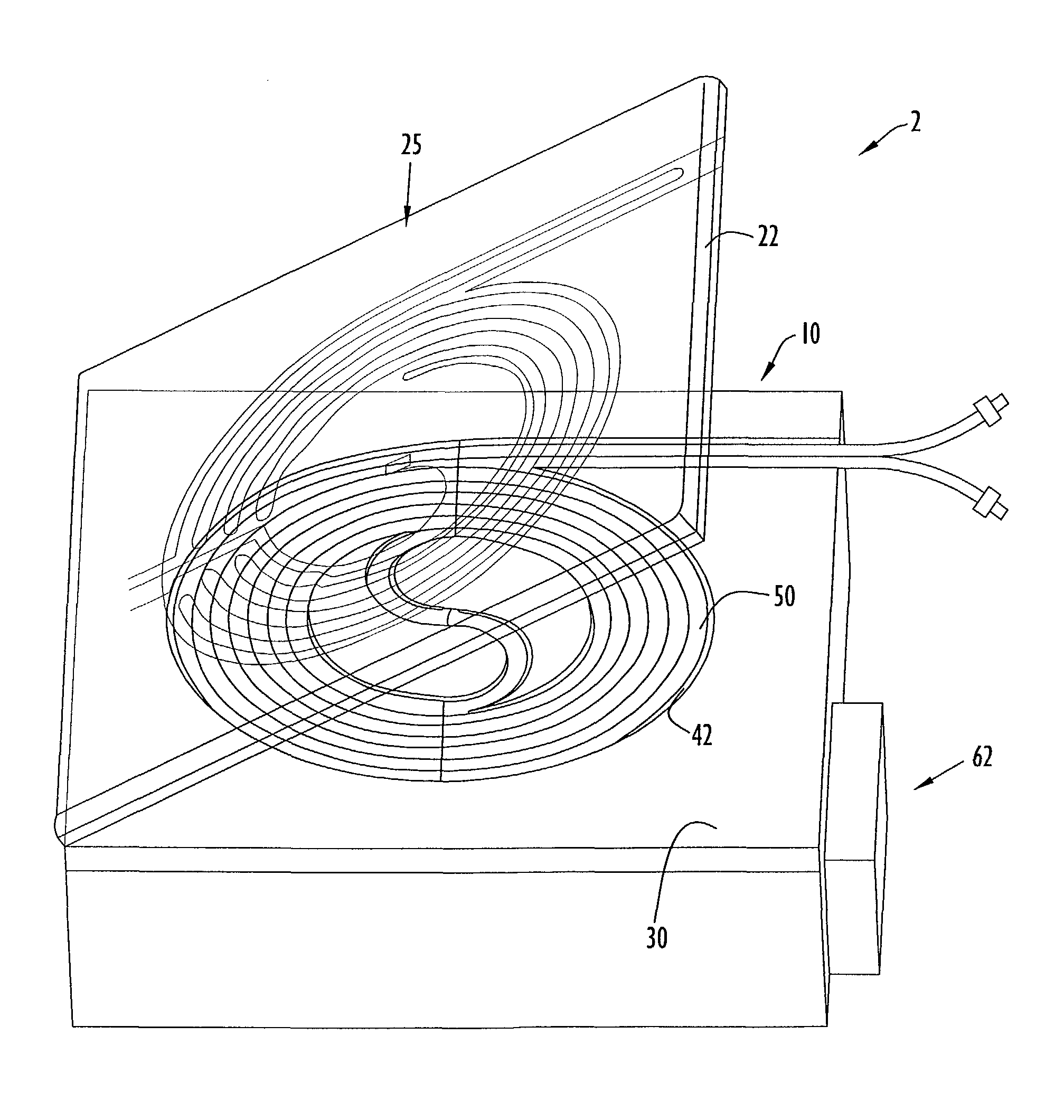
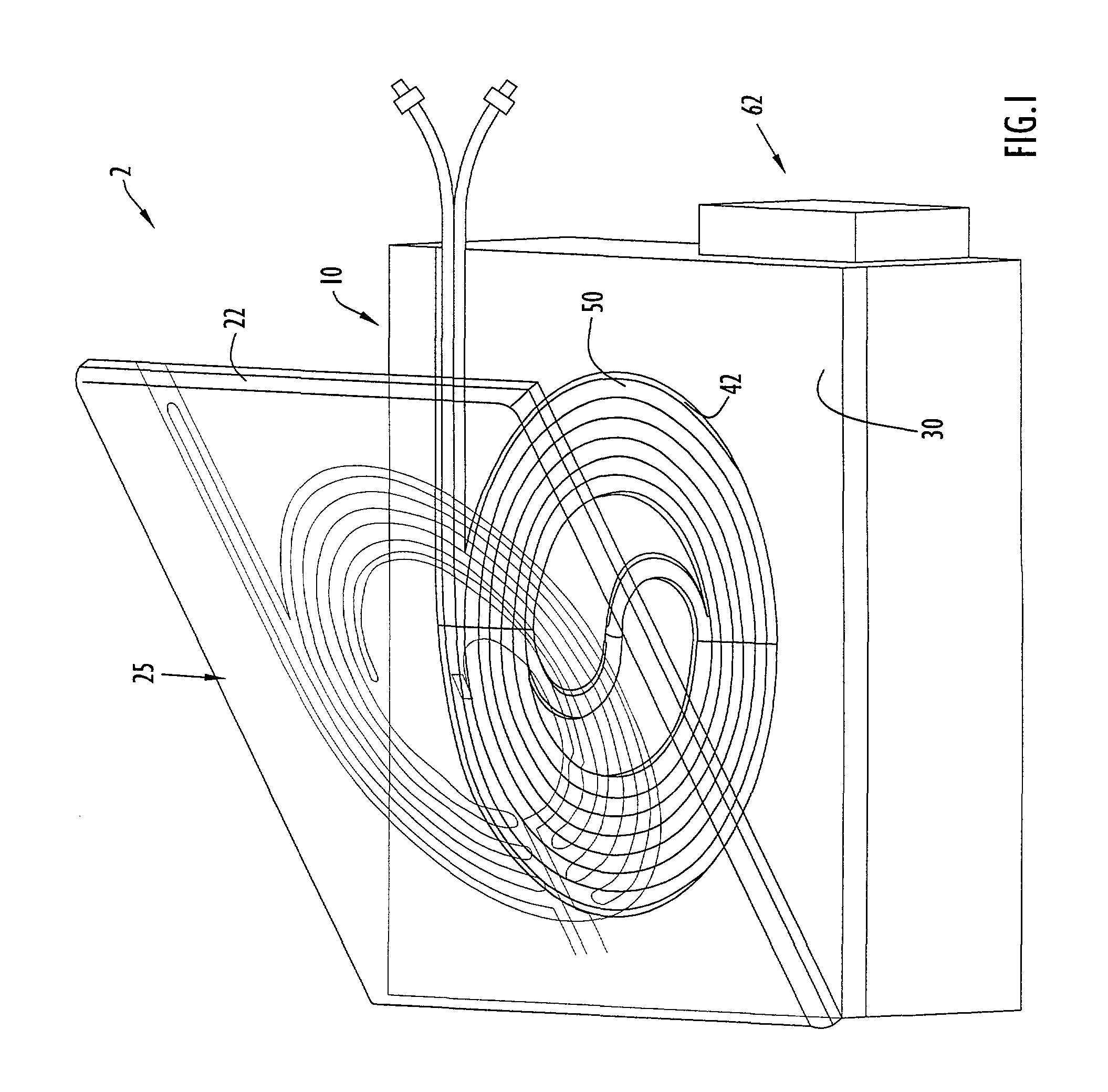
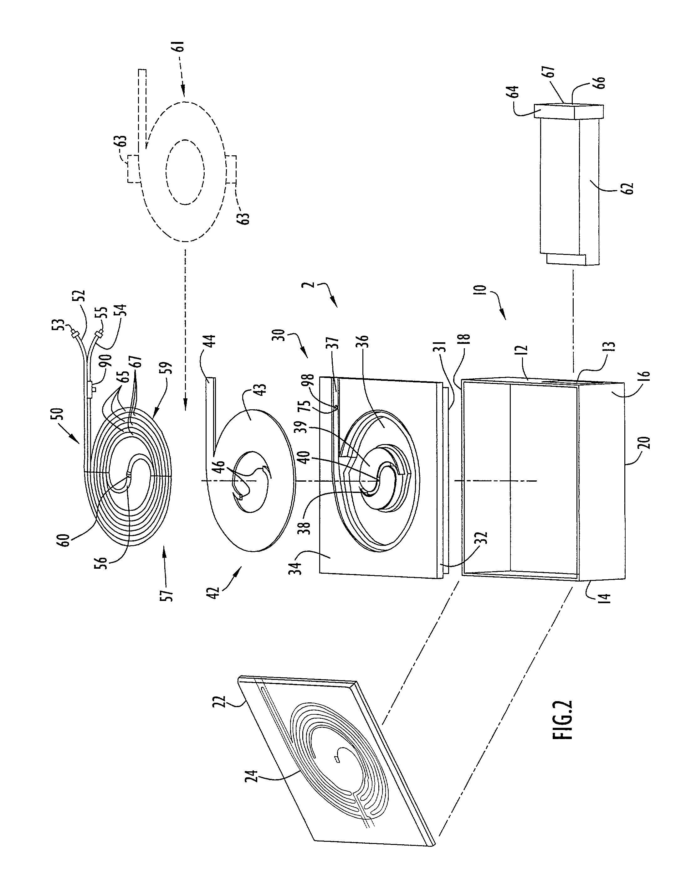
[0027]An IV line temperature controlled warming device for heating and maintaining fluids flowing within an IV fluid line at desired temperatures is illustrated in FIG. 1. Specifically, warming device 2 includes a housing 10 with a lid or cover 22 pivotally attached thereto. The warming device receives a tubing cassette or cartridge 50 that is typically connected to an intravenous line (IV) supplying intravenous solution from an IV solution bag or container to a patient. The device housing includes a base plate 30 to receive cassette 50 and a heater plate 42 disposed on the base plate beneath the cassette to heat a cassette bottom surface as described below. An additional heater or heating element 25 is disposed on cover 22 to heat the cassette top surface as described below. Thus, the cassette is disposed between the heater plate and cover heating elements to receive heat on opposing cassette surfaces for uniform heating of solution or other fluid flowing therein. A controller 62 i...


PUM


Abstract

An IV line temperature controlled warming device includes a housing and a fluid cassette or cartridge that receives fluid from an IV line and includes intravenous line tubing arranged in a preformed configuration. The configuration includes tubing sections arranged in generally circular and concentric portions and a central serpentine tubing section that basically reverses fluid flow and facilitates flow in opposing directions within adjacent tubing sections. The fluid cassette is retained within the device on a base plate partially disposed within a device housing interior, while a housing cover is selectively opened and closed to permit access to the base plate. The base plate includes a heater plate disposed thereon, while the cover and heater plate each include heating elements to apply heat to opposing surfaces of the tubing cassette. The heating elements are controlled by a controller in response to measured temperatures of the heater plate and fluid.

Description

BACKGROUND OF THE INVENTION[0001]1. Technical Field[0002]The present invention pertains to devices for warming intravenous (IV) solution during infusion into a patient. In particular, the present invention pertains to a device for receiving and heating a preformed IV tubing cassette or cartridge connected to an IV line to warm solution flowing within the line to a desired temperature during infusion into a patient.[0003]2. Discussion of Related Art[0004]Intravenous (IV) fluids are typically infused into a patient utilizing a liquid filled bag or container and an IV fluid line. The fluids are generally delivered from the container to the patient via gravitational forces and / or applied pressure. It is important in many situations that the temperature of the fluid within the IV line be maintained within a desirable and safe temperature range upon entering the patient body so as to eliminate any potential for thermal shock and injury to the patient.[0005]Accordingly, the related art pro...

Claims


Application Information

Patent Timeline
Patent Type & Authority Patents(United States)
IPC IPC(8): A61F7/12A61M5/14A61M5/44
CPCA61M5/44A61M2205/3653A61M5/1415A61M2205/3368A61M2205/14
Inventor FARIES, JR., DURWARD I.HEYMANN, BRUCE R.BLANKENSHIP, CALVINHENDRIX, DAVID
Owner MEDICAL SOLUTIONS INC
Why Eureka
Try Eureka