Apparatus and method for bearing condition monitoring

a technology of bearing condition and apparatus, applied in the field of bearing current monitoring system and method, can solve the problems of rotating machines, discontinuities in the surface, rotating machines, and typically susceptible to abnormal bearing wear and tear

Active Publication Date: 2012-07-24
GENERAL ELECTRIC CO
View PDF18 Cites 63 Cited by
  • Summary
  • Abstract
  • Description
  • Claims
  • Application Information

AI Technical Summary

Problems solved by technology

Rotating machines such as electrical motors typically include bearings that support a shaft, and such rotating machines are typically susceptible to abnormal bearing wear due to bearing current.
Typically, rotating machines may be susceptible to various known sources of shaft voltage that can lead to bearing currents such as electromagnetic induction, electrostatic coupling from internal sources, and electrostatic coupling from external sources.
These currents can cause premature failure of the bearings in the rotating machine by causing an electrical discharge to pass through the bearing balls and races, causing metal transfer therefrom and into the lubricant.
This loss of metal leads to pitting, craters, and discontinuities in the surfaces, which leads in turn to increased bearing currents.
The increased bearing currents effect tends to increase frictional heating, to increase temperature of the bearing during operation, and ultimately to cause failure of the bearing.
As such, the increased frequencies of operation exacerbate the problem of current flow within the bearings, thus leading to early life failure.
Thus, despite efforts to improve motor design and reduce the propensity for early life failure, the bearings nevertheless experience currents passing therethrough that is worsened due to high frequency operation.
However, such methods typically involve the use of brushes or expensive external equipment, and such external equipment may only yield an indirect indication of bearing condition, such as acoustic noise, as an example.

Method used


Image

  • Apparatus and method for bearing condition monitoring
  • Apparatus and method for bearing condition monitoring
  • Apparatus and method for bearing condition monitoring

Examples


Embodiment Construction

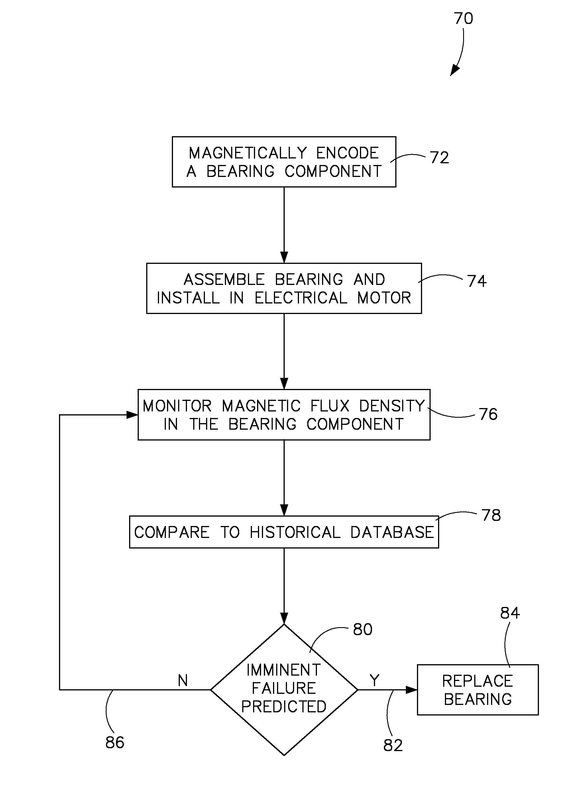
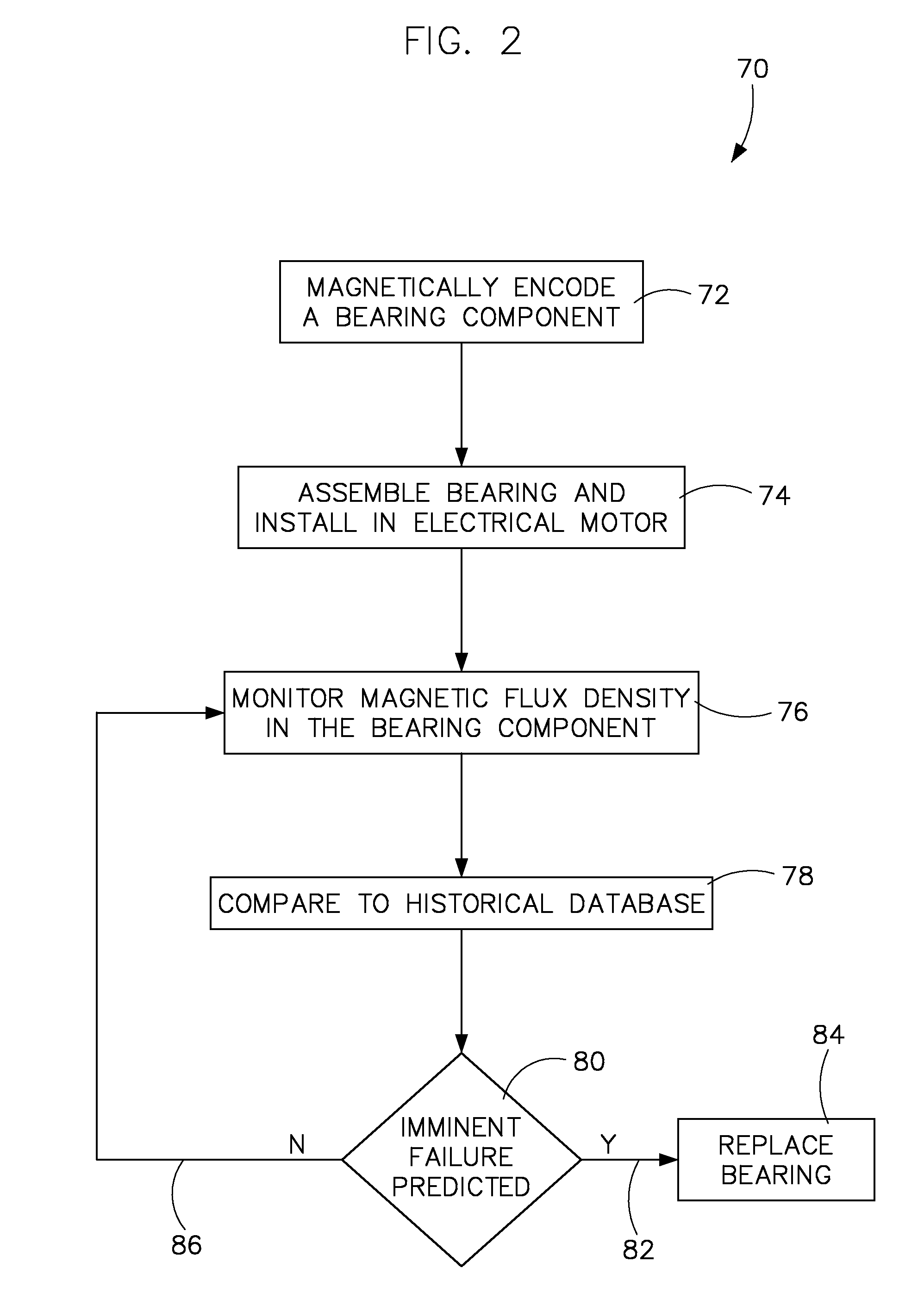
[0022]A system and method are shown for monitoring a condition of a bearing in an electrical motor. However, one skilled in the art will recognize the invention is equally applicable to other rotating devices that result in electrical current passing through balls of a bearing. Thus, although the invention is described in embodiments that include an electrical motor, one skilled in the art will recognize that the invention presented herein need not be limited to an electrical motor, but may include any rotating device having bearings therein that are susceptible to bearing currents passing therethrough. Further, as will be illustrated, embodiments of the invention described herein include a ring that is magnetically encoded and coupled or otherwise attached to one or more bearing races. However, additional embodiments, as will be discussed, include races or other components that are themselves ferromagnetic materials that may be magnetically encoded, thus forgoing a separate magneti...


PUM


Abstract

An electrical motor bearing condition monitoring system includes an assembly that includes a shaft, a first bearing race coupled to the shaft, a plurality of bearing balls, and a second bearing race coupled to the first bearing race via the plurality of bearing balls. A portion of the assembly has a magnetic field encoded thereon. The monitoring system includes a magnetic field sensor positioned proximately to the magnetized assembly and configured to measure the magnetic field, and a processing unit configured to detect changes in the magnetic field via the magnetic field sensor.

Description

BACKGROUND[0001]The invention relates generally to bearing currents and, more specifically, to a system and method of monitoring a condition of a bearing.[0002]Rotating machines such as electrical motors typically include bearings that support a shaft, and such rotating machines are typically susceptible to abnormal bearing wear due to bearing current. Typically, rotating machines may be susceptible to various known sources of shaft voltage that can lead to bearing currents such as electromagnetic induction, electrostatic coupling from internal sources, and electrostatic coupling from external sources. The current may manifest itself as an axial flux passing down the center of the motor shaft or as an alternating flux linking the motor shaft, as examples. Bearing currents may arise whether the machine is DC or AC, and whether the machine is a large or a small horsepower motor.[0003]Axial shaft flux is created by unbalanced ampere turns that encircle the shaft, by a broken rotor bar,...

Claims


Application Information

Patent Timeline
Patent Type & Authority Patents(United States)
IPC IPC(8): G01M13/04G06F19/00
CPCF16C19/52F16C41/007G01M13/04H02K11/001H02K7/08H02K5/16H02K11/20
Inventor EL-REFAIE, AYMAN MOHAMED FAWZIKING, ROBERT DEANSIHLER, CHRISTOF MARTIN
Owner GENERAL ELECTRIC CO
Why Eureka
Try Eureka