
Stuffing apparatus and casing breakage detecting device for stuffing apparatus

a detection device and stuffing technology, applied in the direction of sausage casings, sausage shirrings, applications, etc., can solve the problems of more material being discharged to the outside, more material being discharged, waste, etc., to prevent the adhesion of material, prevent non-detectability, and enhance the degree of freedom of an installation place

Active Publication Date: 2012-07-31
HITEC
View PDF20 Cites 2 Cited by
  • Summary
  • Abstract
  • Description
  • Claims
  • Application Information

AI Technical Summary

Benefits of technology

[0023]The present invention has been devised in view of the above-described aspects, and its object is to provide a stuffing apparatus which makes it possible to enhance the degree of freedom of an installation place of a detecting device for detecting a casing breakage during the operation of the stuffing apparatus, to thereby prevent the adhesion of the material to prevent nondetectability, and which makes a special supporting means unnecessary and reduces the time period until an ensuing operation after the casing breakage.
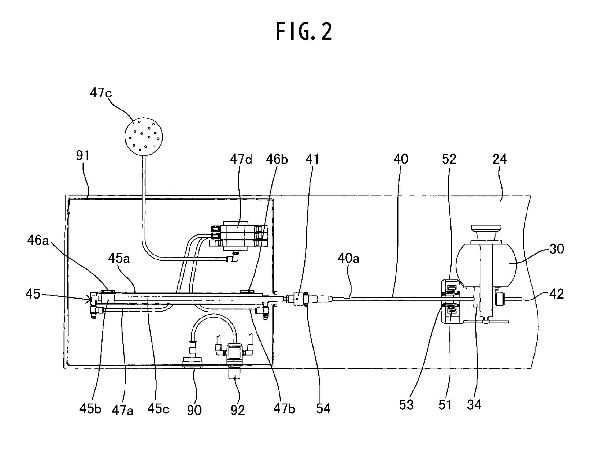
[0033]In the present invention, the stoppage of the casing pushing device due to the casing breakage is detected by the movement stop detecting means, such as a flow sensor for detecting the flow rate of air (the flow rate of air becomes substantially zero if the casing pushing device stops) flowing in the air cylinder serving as the fluid cylinder, a pressure sensor for detecting the pressure of air (the air pressure increases if the casing pushing device stops) within an air cylinder. In consequence, the amount of the material discharged to the outside can be minimized by stopping at least the stuffing pump or all of the pincher device, the stuffing nozzle, the braking member, the air cylinder, and the stuffing pump (hereafter, the phrase “at least the stuffing nozzle” and the phrase “all of the pincher device, the stuffing nozzle, the braking member, the air cylinder, and the stuffing pump” will be rephrased as the stuffing pump and the like).
[0034]In addition, since the amount of material discharged to the outside can be minimized, the time period until an ensuing operation after the casing breakage can be reduced, thereby making it possible to minimize a decline in production efficiency.
[0035]Further, since the movement stop detecting means can be provided in an air passage communicating with the air cylinder, it is possible to enhance the degree of freedom of the installation place. Still further, since at least one of a flow sensor and a pressure sensor which are commercially available can be mounted on an existing apparatus by a simple mounting means, it is possible to suppress the surging of the production cost. Furthermore, even if a casing breakage occurs, since the movement stop detecting means is provided not in the vicinity of the discharge port of the stuffing nozzle but at a location rearwardly far distant from the vicinity of the discharge port of stuffing nozzle (the movement stop detecting means may be provided even in a box as in the embodiment), the adhesion of the splattered material thereto is practically nil (the adhesion becomes totally nil if it is provided in the box as in the embodiment). Hence, it is possible to further reduce the time period until an ensuing operation after the casing breakage.
[0037]According to the above-described fourth aspect of the invention, the controller stops the stuffing pump and the like in the case where the stoppage of the casing pushing device which is continuous for a predetermined time duration is detected by the movement stop detecting means. Hence, it is possible to prevent a decline in production efficiency as described above.

Problems solved by technology

For this reason, if any slight damage is caused to the casing such as when the casing is stretched, there are cases where the damage during the stuffing of the material spreads, and the casing becomes ruptured and breaks.
Particularly in the case of automatic operation, an operator, upon noticing a casing breakage, will press a stop switch, but the time duration when the operator is away from the stuffing apparatus is often long, so that the operator is inevitably apt to be delayed in noticing such a casing breakage.
A further delay in noticing results in more material being discharged to the outside and wasted, and time and trouble are required in cleaning up the discharged material, causing production efficiency to decline correspondingly.
This being the case, however, the material continues to be discharged to the outside until the operator presses the stop switch after noticing, so that the material is wasted by that quantity.
The time and trouble for cleaning up the discharged material are also required, so that there is still a problem in that the production efficiency declines.
However, the place of installation of the sensor is difficult to secure above the discharge port of the stuffing nozzle, and even if it is possible to secure the place of installation of the sensor, there arises a need to provide an exclusive sensor supporting means consisting of, for example, an L-shape or the like and to mount the sensor on that supporting means.
Therefore, the production cost increases correspondingly.
In addition, the vicinity of the discharge port of the stuffing nozzle is a place where an operation by the operator is performed at the time of setting a new casing on the stuffing nozzle, so that there is a large risk that the material and the like attached to the operator's hand or the like become splattered.
Furthermore, with the apparatus disclosed in the above-described JP-UM-B-6-29989, in the event that the casing is ruptured and the material is splattered, there is a large risk of the material adhering to the sensor.
Since that much time is involved until the ensuing operation, there is a problem in that the production efficiency declines.
The apparatus disclosed in JP-T-2004-524008 also has a virtually similar problem.
Although the sensor is mounted on a cover 26, an exclusive sensor supporting means is required for mounting it, so that the production cost increases correspondingly.
In addition, as described above, the surrounding area of the pincher device is a place where there is a large risk of the material or the like being splattered, so that the apparatus disclosed in JP-T-2004-524008 also has a possibility that the material or the like is adhered to the sensor during the stuffing operation, thereby making detection impossible.
Since that much time is involved until the ensuing operation, there is also the problem that the production efficiency declines.
Hence, the production cost increases correspondingly.
Furthermore, there is a possibility that the detecting portion of the sensor becomes stained by the material or the like, rendering detection difficult.
However, in the same way as the apparatus disclosed in JP-A-8-103206, the apparatus disclosed in U.S. Pat. No. 4,602,402 also requires a device for converting the advancing of the casing into a pulse signal, so that the structure becomes complex by that portion, and the production cost increases correspondingly.

Method used


Image

  • Stuffing apparatus and casing breakage detecting device for stuffing apparatus
  • Stuffing apparatus and casing breakage detecting device for stuffing apparatus
  • Stuffing apparatus and casing breakage detecting device for stuffing apparatus

Examples


Embodiment Construction

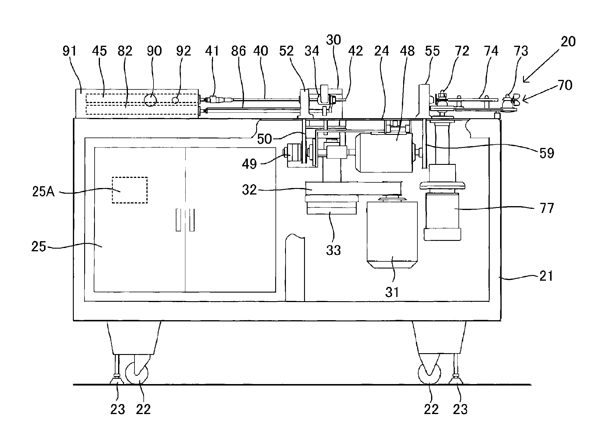
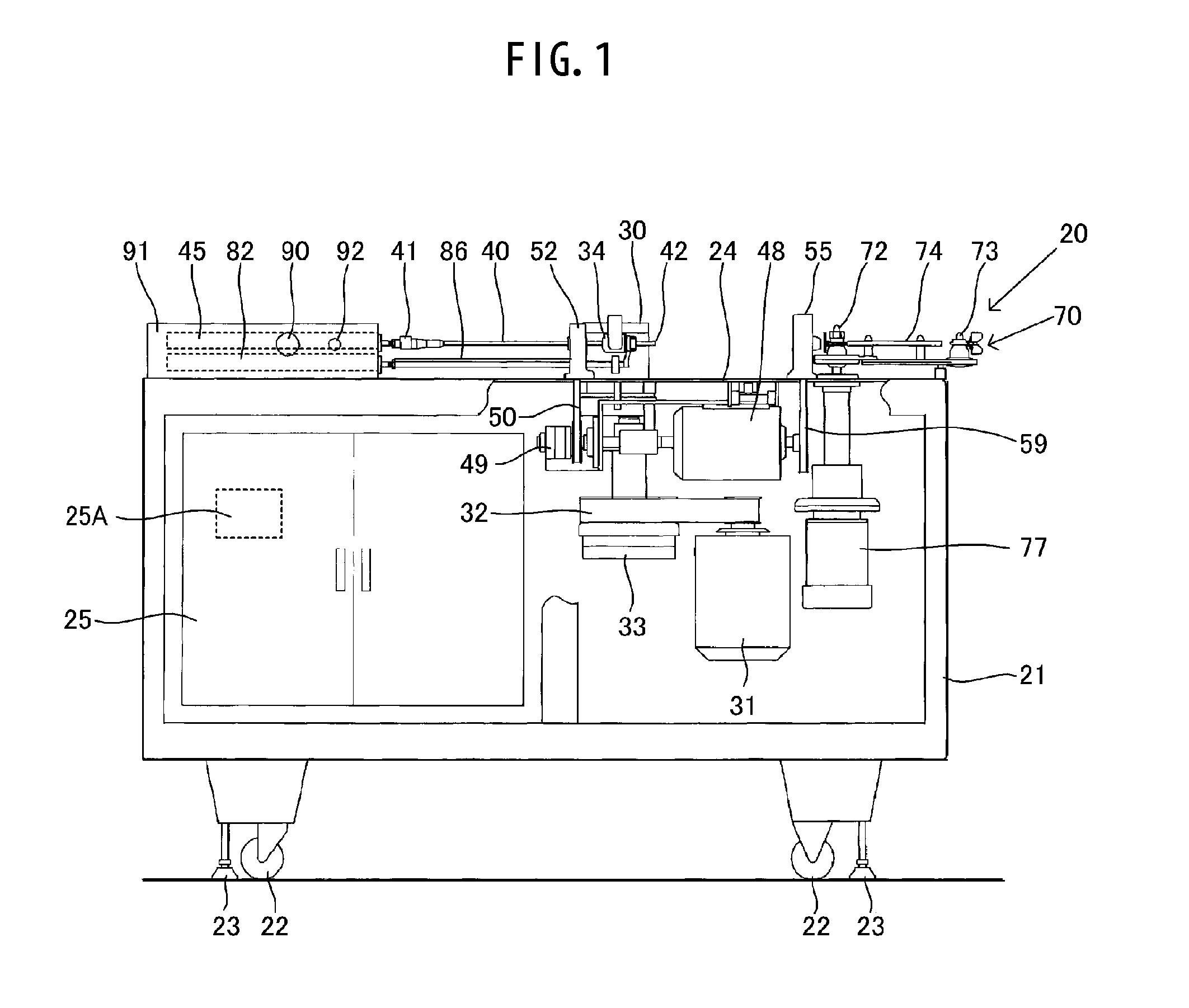
[0054]Referring now to the accompanying drawings, a detailed description will be given of the embodiment of the invention. It should be noted that it is assumed that, in FIG. 1, the side of a casing pushing air cylinder 82 is a rear side, and the side of a pincher device 70 is a front side.

[0055]A stuffing apparatus 20 has a box-shaped case member 21. The case member 21 is provided with legs 22 and stoppers 23 on its bottom portion and is hence movable. Mounted on its upper surface, i.e., a mounting base 24, are a stuffing pump 30, a stuffing nozzle 40, a braking mechanism 56, a pincher device 70, and the like which constitute the stuffing apparatus 20.

[0056]The stuffing pump 30 feeds a material such as meat, i.e., a stuffing material, into the stuffing nozzle 40. A speed-variable stuffing pump motor 31, a belt 32, an electromagnetic clutch 33, and the like, which constitute the driving mechanism of the stuffing pump 30, are provided in the case member 21 below the mounting base 24....


PUM


Abstract

A stuffing apparatus includes: a stuffing nozzle for discharging a stuffing material from a discharge port into a casing; a stuffing pump for feeding the stuffing material into the stuffing nozzle; a casing pushing device which has a casing pusher and a fluid cylinder having a cylinder, a piston, and a rod, and which is adapted to push in a direction toward the discharge port of said stuffing nozzle a trailing end portion of a casing which is yet to be stuffed and is in a shirred state; and a movement stop detecting device (casing breakage detecting device) for detecting stoppage of the casing pushing device in the course of its movement.

Description

BACKGROUND OF THE INVENTION[0001]1. Field of the Invention[0002]The present invention relates to a device for indirectly detecting a casing breakage during material stuffing in a stuffing apparatus for manufacturing sausages, fish feeds, or the like.[0003]2. Description of the Related Art[0004]Sausage products are manufactured by stuffing a material such as meat, i.e., a stuffing material, into an artificial casing such as a cellulose casing or a collagen casing or a casing of an animal intestine such as a sheep intestine or a hog intestine. In addition, sausage-like assorted feeds in which a material stuffed in a collagen casing are manufactured as feeds for cultured tuna.[0005]FIG. 15 shows a conventional stuffing apparatus. A stuffing apparatus 1 includes, among others, a stuffing nozzle 3 for feeding a material such as meat, i.e., the stuffing material, into a casing 2; a stuffing pump 4 for feeding the material into the stuffing nozzle 3; a stuffing nozzle rotating means 5 for ...

Claims


Application Information

Patent Timeline
Patent Type & Authority Patents(United States)
IPC IPC(8): A22C11/04A22C11/06A23L13/60A23L17/00
CPCA22C11/0245
Inventor NAKAMURA, TATSUOKAMAKURA, YOSHINORI
Owner HITEC
Learn More