Method of producing gas barrier film

a gas barrier film and film deposition technology, applied in the direction of chemical vapor deposition coating, coating, plasma technique, etc., can solve the problems of difficult deposition of silicon nitride layer on less heat-resistant resin film, gas barrier film obtained by film deposition at such a low temperature has very often no desired performance, and device cost is considerabl

Active Publication Date: 2012-08-07
FUJIFILM CORP
View PDF15 Cites 1 Cited by
  • Summary
  • Abstract
  • Description
  • Claims
  • Application Information

AI Technical Summary

Benefits of technology

[0022]From the viewpoint that the effects of the invention can be exhibited more advantageously, various films having low heat resistance are preferably used for the substrate Z, and examples thereof that may be suitably used include resin films (plastic films) having a glass transition temperature of not more than 70° C. such as polyethylene terephthalate (PET) films.
[0023]In the present invention, the substrate Z may be such that it has any of the various films, on the surface (on at least the film deposition surface) of which are formed layers (films) that are made of organic materials or inorganic materials to provide various functions (e.g., a protective layer, an adhesive layer, a light reflecting layer, a light shield layer, a planarizing layer, a buffer layer, and a stress relaxing layer).
[0024]The vacuum chamber (process chamber) 12 is a known vacuum chamber employed in various vacuum film-forming devices such as plasma CVD devices, sputtering devices, and vacuum deposition devices.
[0025]Exemplary means that may be used for the vacuum evacuation means 28 include vacuum pumps such as a turbo pump, a mechanical booster pump and a rotary pump, an assist means such as a cryogenic coil, and various other (vacuum) evacuation means which use a means for adjusting the ultimate degree of vacuum or the amount of discharge air.
[0026]The substrate holder 14 is used to hold the substrate Z at a predetermined film deposition position and various substrate holders that may be used in various vacuum film-forming devices are available.
[0027]Although not shown, the substrate holder 14 of the CVD device 10 has a temperature adjusting means incorporated therein to keep the temperature of the substrate Z at 70° C. or less during deposition of a silicon nitride layer.

Problems solved by technology

JP 2005-342975 A uses a polyethersulfone film for the substrate and deposits a silicon nitrate layer at a substrate temperature of 150° C., but it is difficult to deposit a silicon nitride layer on a less heat-resistant resin film such as an inexpensive polyethylene terephthalate (PET) film at the substrate temperature of 150° C.
However, gas barrier films obtained by film deposition at such a low temperature very often have no desired performance.
In addition, a film deposition pressure of 10 Pa requires a sophisticated film deposition device, and particularly in cases where improvement of the productivity, that is, improvement of the flow rate of a material gas is desired, involves a considerable increase in device cost.

Method used


Image

  • Method of producing gas barrier film
  • Method of producing gas barrier film

Examples


example 1

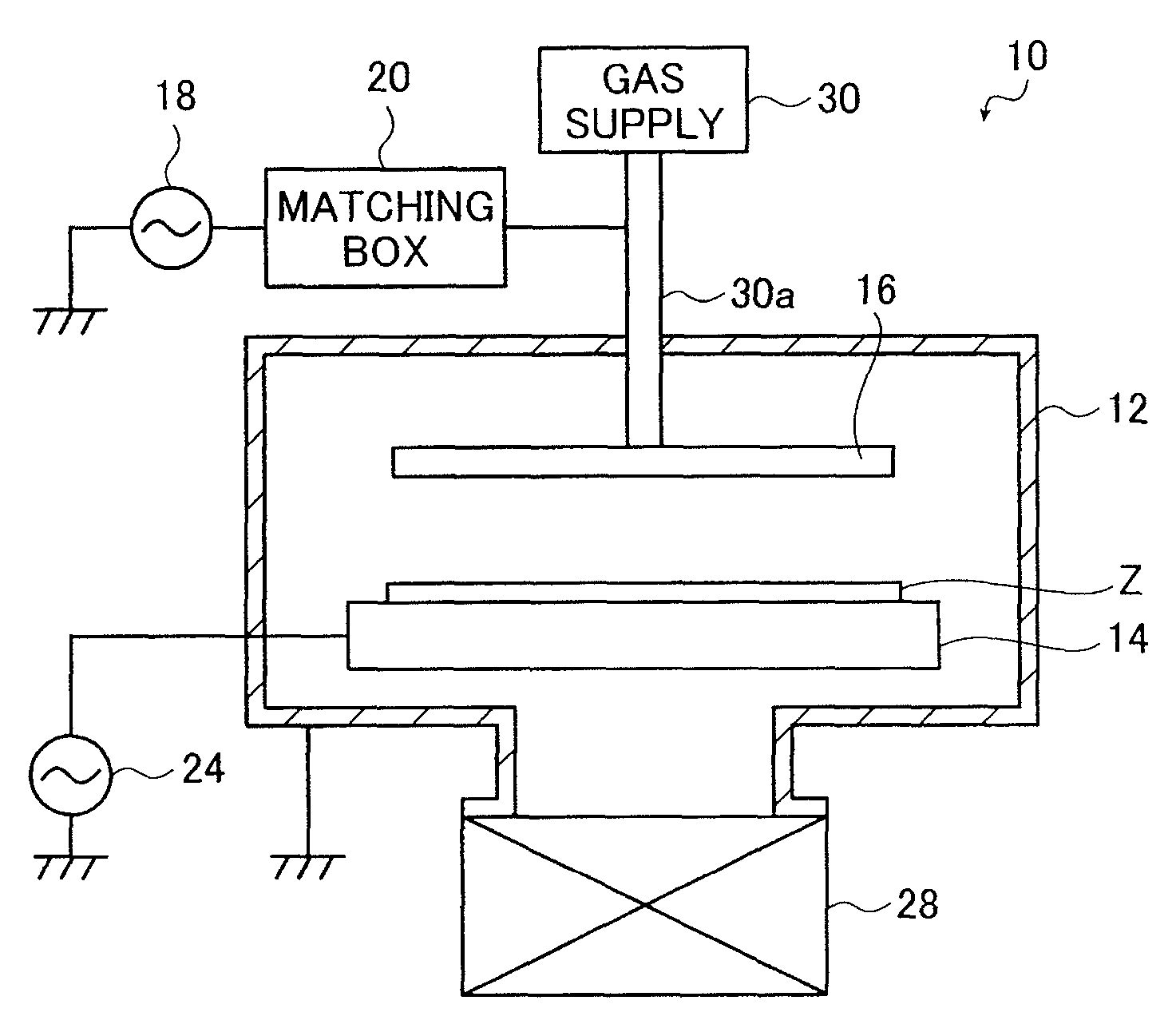
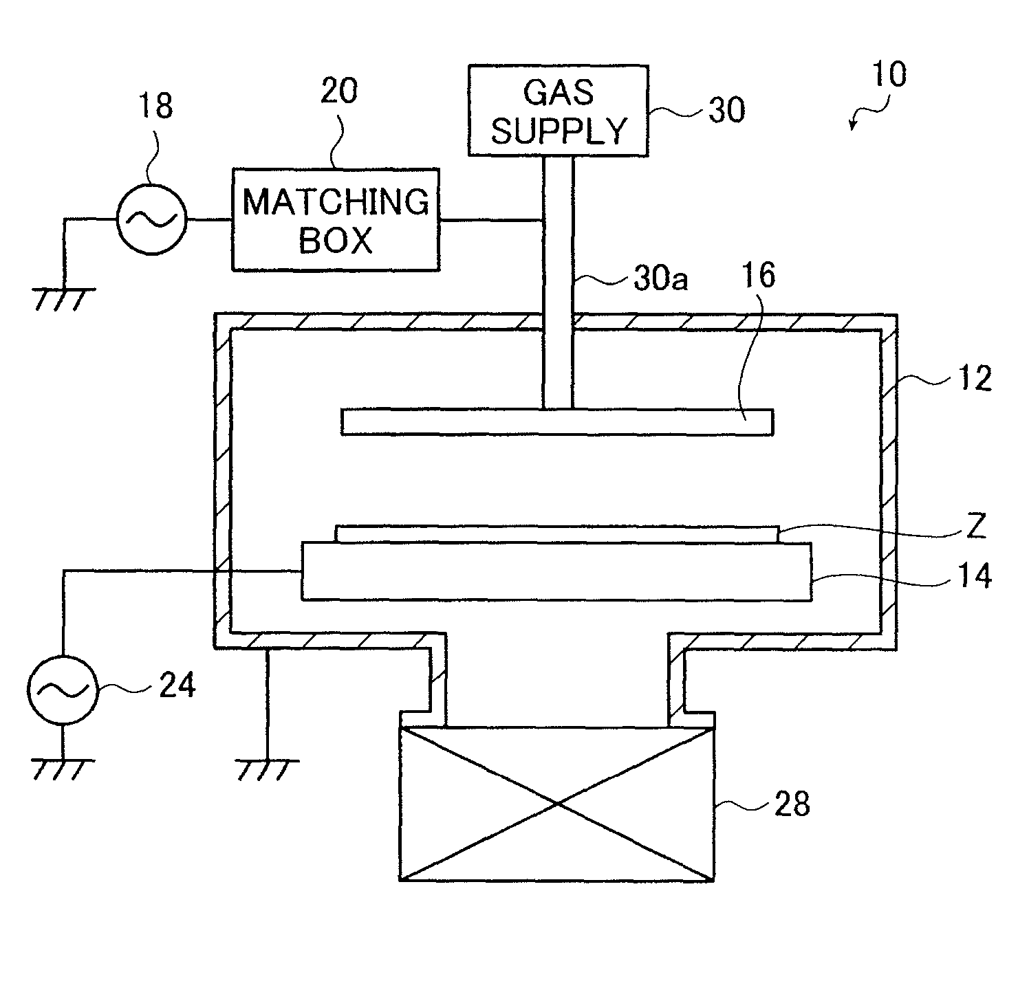
[0093]The CVD device 10 shown in the FIGURE was used to deposit a silicon nitride layer with a thickness of 100 nm on the surface of a substrate Z, thus producing a gas barrier film.

[0094]The substrate Z used was a PET film (Cosmoshine A430 available from Toyobo Co., Ltd.) with a thickness of 100 μm.

[0095]The substrate Z was disposed at a predetermined position on the substrate holder 14 and the vacuum chamber 12 was closed. The substrate holder 14 was made of aluminum and had a refrigerant circulating system incorporated therein as the temperature adjusting means.

[0096]The temperature adjusting means incorporated in the substrate holder 14 was driven so that the substrate Z had a temperature of 70° C. The temperature adjusting means measured the temperature of the substrate holder 14 to control the temperature of the substrate Z by feedback control so that its temperature was kept at 70° C. The substrate holder 14 was made of aluminum having high heat conductivity and the substrate...

example 2

[0103]Example 1 was repeated except that the power supplied from the RF power source 18 to the shower head electrode 16 was changed to 750 W, in other words, the ratio P / Q was changed to 15 W / sccm, thereby producing a gas barrier film.

example 3

[0104]Example 1 was repeated except that the power supplied from the RF power source 18 to the shower head electrode 16 was changed to 1500 W, in other words, the ratio P / Q was changed to 30 W / sccm, thereby producing a gas barrier film.


PUM

PropertyMeasurementUnit
internal pressureaaaaaaaaaa
temperatureaaaaaaaaaa
bias potentialaaaaaaaaaa

Abstract

A method of producing a gas barrier film comprises the steps of: supplying a material gas including silane gas, ammonia gas and at least one of nitrogen gas and hydrogen gas to a process chamber; keeping the process chamber at an internal pressure of 20 to 200 Pa; holding a substrate in the process chamber at a substrate temperature of not more than 70° C.; forming a bias potential of −100 V or less at the substrate; and supplying power P (W) to the material gas so as to have a ratio P / Q of the power P to a silane gas flow rate Q (sccm) of 15 to 30 W / sccm to generate plasma, thereby depositing a silicon nitride layer on a surface of the substrate.

Description

[0001]This application claims priority to Japanese Patent Application No. 2008-229581, filed Sep. 8, 2008, the disclosure of which is incorporated herein by reference in its entirety. In addition, the entire contents of all patents and references cited in this specification are also incorporated herein by reference.BACKGROUND OF THE INVENTION[0002]The present invention relates to a method of producing a gas barrier film making use of capacitively coupled plasma-enhanced chemical vapor deposition, and more specifically relates to a gas barrier film production method capable of producing a gas barrier film having good gas barrier properties using a less heat-resistant substrate.[0003]Gas barrier films having a silicon nitride layer deposited on the surface of a resin (plastic) film are known as gas (water vapor) barrier films employed in various apparatuses and optical devices which are required to be moisture-proof.[0004]Capacitively coupled plasma-enhanced chemical vapor deposition ...

Claims


Application Information

Patent Timeline
Patent Type & Authority Patents(United States)
IPC IPC(8): H05H1/24
CPCC23C16/345C23C16/509H01J37/32091H01J37/32706
Inventor FUJINAMI, TATSUYATAKAHASHI, TOSHIYA
Owner FUJIFILM CORP
Why Eureka
Try Eureka