Minimally invasive rectal balloon apparatus

a rectal balloon and minimally invasive technology, applied in the field ofrectal balloons, can solve the problems of insufficient radiation treatment, difficult prostate cancer treatment using radiation therapy, and inability to accurately determine the position of the balloon

Active Publication Date: 2012-08-14
ANGIODYNAMICS INC
View PDF63 Cites 10 Cited by
  • Summary
  • Abstract
  • Description
  • Claims
  • Application Information

AI Technical Summary

Problems solved by technology

Treatment of prostate cancer using radiation therapy is difficult due to the prostate's position near radiation-sensitive tissues, and is further complicated by prostate motion.
A misdirected radiation beam may perforate the rectal wall causing radiation proctitus (rectal bleeding).
However, this may lead to inadequate radiation treatment and a higher probability of local cancer recurrence.
One of the problems with the subject of U.S. Patent Publication No. 2003 / 0028097 is the discomfort associated installing the rectal balloon within the rectal cavity.
Because of the relatively large size of the shaft and the thick material of the rectangular-cross section balloon, the installation of the rectal balloon creates a large amount of discomfort for a patient.
It is often difficult for the medical personnel to know exactly how far within the rectum the balloon has been installed.
It is difficult to achieve a standardized and fixed position of the balloon during each and every use.

Method used


Image

  • Minimally invasive rectal balloon apparatus
  • Minimally invasive rectal balloon apparatus
  • Minimally invasive rectal balloon apparatus

Examples


Embodiment Construction

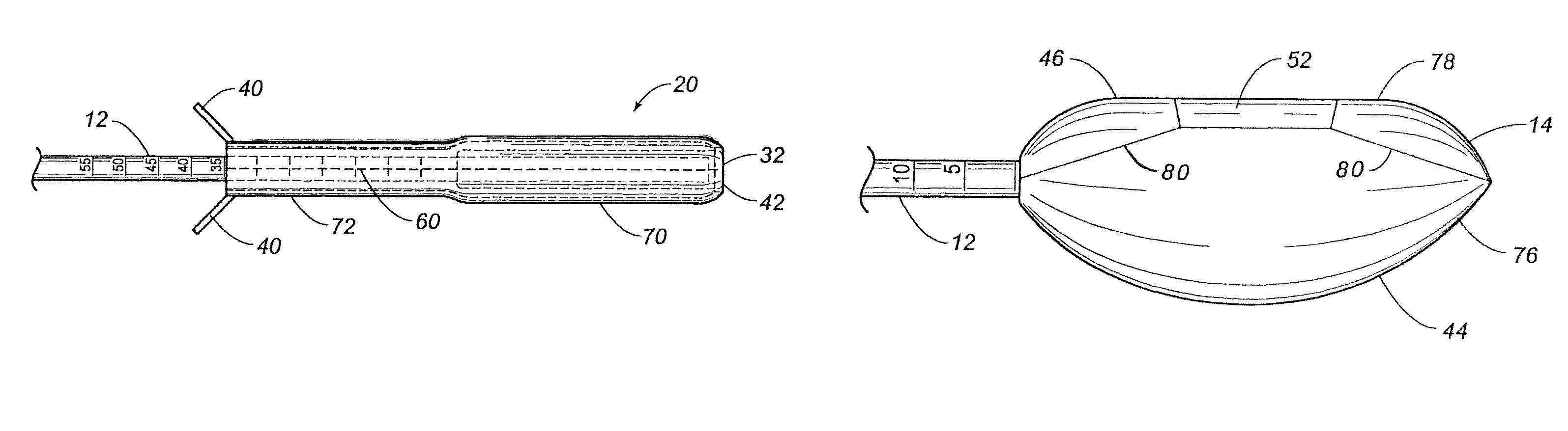
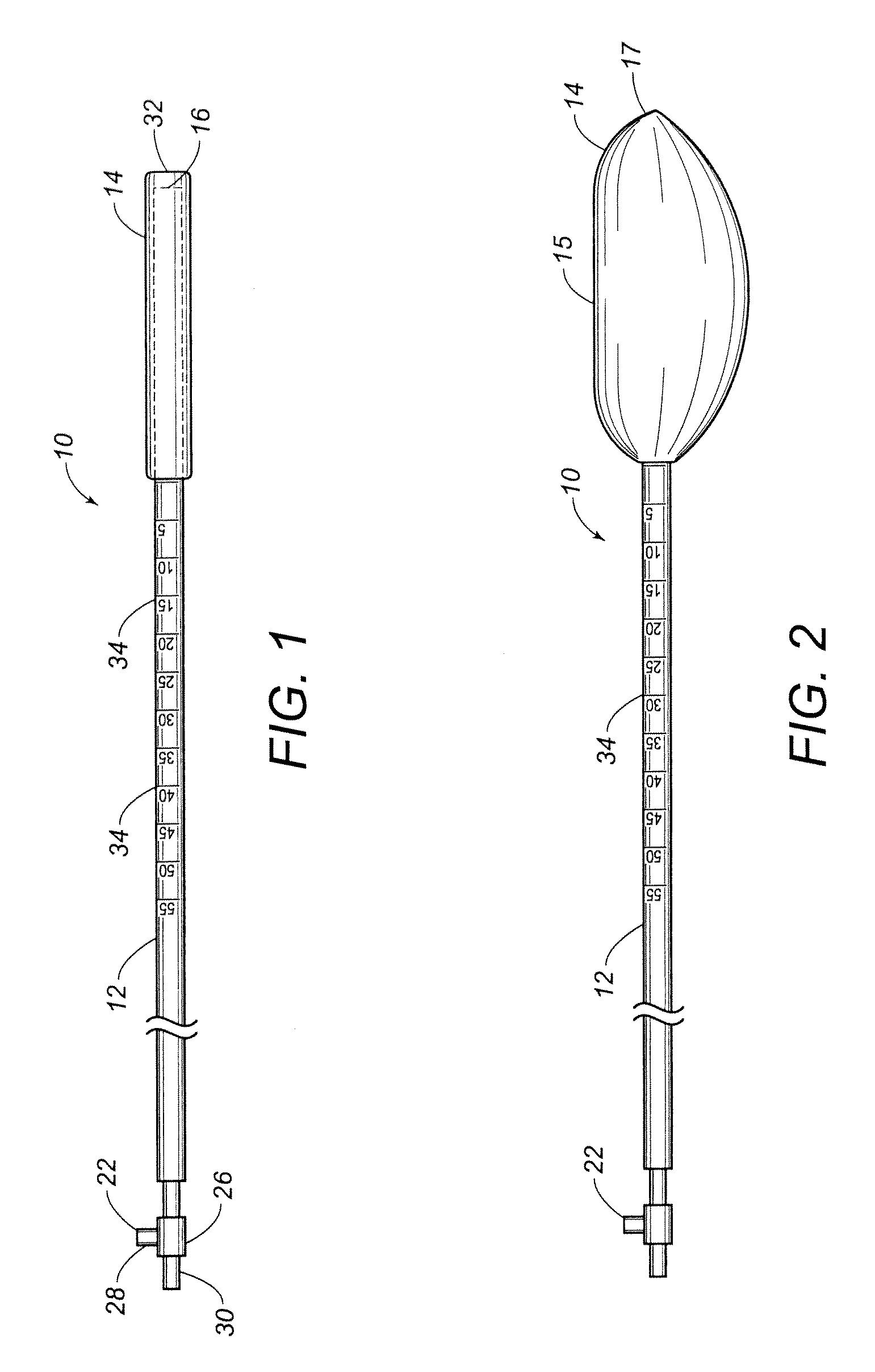
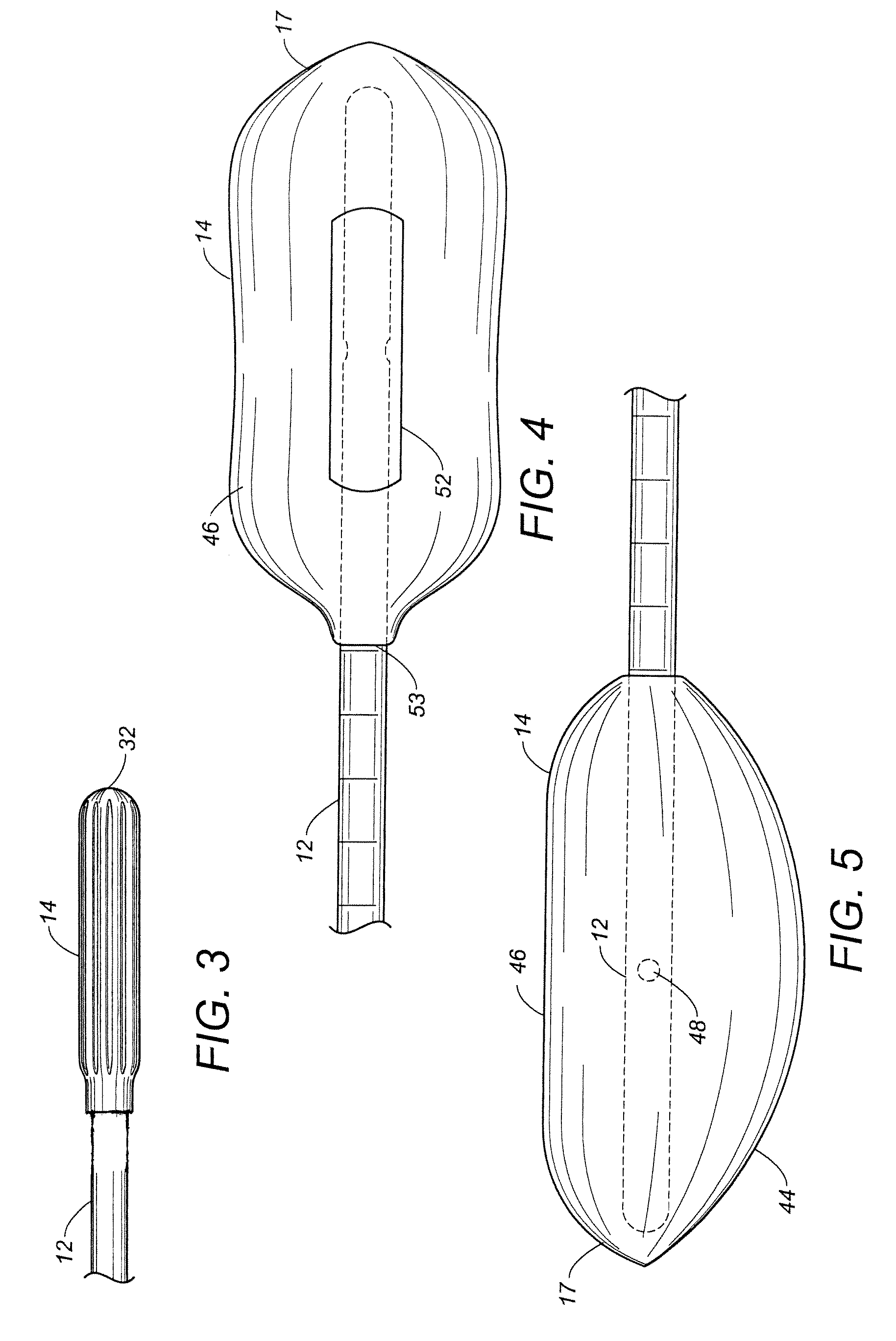
[0042]Referring to FIG. 1, there is shown the rectal balloon apparatus 10 in accordance with the preferred embodiment. The rectal balloon apparatus 10 includes a shaft 12 having a fluid passageway extending therethrough. A balloon 14 is affixed over the end 16 of the shaft 12. The balloon 14 is shown in an uninflated condition. The fluid passageway of the shaft 12 can communicate with the interior of the balloon 14.

[0043]The shaft 12 is a generally longitudinal shaft which has the fluid passageway extending through the center thereof. The shaft 12 is made of a flexible material. A valve assembly 22 is affixed to the shaft 12 opposite the balloon 14. The valve assembly 22 can have a variety of configurations. FIG. 1 illustrates the valve assembly 22 as an inline valve assembly configuration. The valve assembly 22 may also be an angled valve assembly configuration. The valve assembly 22 includes a stop cock 26. A valve 28 facilitates the ability of the stop cock 26 to open and close s...


PUM


Abstract

A rectal balloon apparatus has a shaft with a fluid passageway extending therethrough. A balloon is affixed over an end of the shaft such that the fluid passageway communicates with an interior of the balloon. The balloon has a laterally flat surface thereon when inflated. The laterally flat surface of the balloon has a longitudinal groove formed thereon. A valve assembly is affixed to the shaft at an end opposite the balloon. The valve assembly selectively allows a fluid to pass therethrough to move the balloon from a non-inflated condition to an inflated condition. A fluid introducing means is removably attached to the valve assembly to introduce the fluid into the valve assembly.

Description

CROSS-REFERENCE TO RELATED APPLICATIONS[0001]This application is a continuation of U.S. application Ser. No. 12 / 034,470, filed on Feb. 20, 2008, now patented as U.S. Pat. No. 8,080,031, which is a continuation-in-part of U.S. application Ser. No. 11 / 933,018 filed on Oct. 31, 2007, now abandoned, which is a continuation-in-part of U.S. application Ser. No. 11 / 623,702 filed on Jan. 16, 2007, now abandoned, which are all hereby incorporated by reference for all purposes in their entirety.STATEMENT REGARDING FEDERALLY SPONSORED RESEARCH OR DEVELOPMENT[0002]N / ANAMES OF PARTIES TO A JOINT RESEARCH AGREEMENT[0003]N / AREFERENCE TO AN APPENDIX SUBMITTED ON COMPACT DISC[0004]N / ABACKGROUND OF THE INVENTION[0005]1. Field of the Invention[0006]The invention relates to rectal balloons that are used for immobilizing the region surrounding the prostate.[0007]2. Description of the Related Art[0008]Treatment of prostate cancer using radiation therapy is difficult due to the prostate's position near ra...

Claims


Application Information

Patent Timeline
Patent Type & Authority Patents(United States)
IPC IPC(8): A61M29/00
CPCA61M29/02A61B2017/00274A61B2017/22069A61B2018/00547A61M2025/0008A61N5/10A61N2005/1097
Inventor ISHAM, JOHNFRIJA, ERIK
Owner ANGIODYNAMICS INC
Why Eureka
Try Eureka