Dielectric antenna

a dielectric antenna and antenna technology, applied in the direction of antennas, liquid/fluent solid measurements, instruments, etc., can solve the problems of contradictory requirements, known dielectric antennae have a further disadvantage, and configuration suitable for hygienic purposes can only be poorly implemented, for exampl

Inactive Publication Date: 2012-08-14
KROHNE MESSTECHNICK GMBH & CO KG
View PDF15 Cites 14 Cited by
  • Summary
  • Abstract
  • Description
  • Claims
  • Application Information

AI Technical Summary

Benefits of technology

[0012]The above object is first and essentially met with the dielectric antenna in question in that the dielectric body has essentially the cross-section of the radiation opening in the area of the supply section. It is, thereby, achieved that the dielectric body is no longer subject to appreciable cross-section changes over its entire extent in the main radiation direction, so that it ultimately fills up the radiation opening in the radiation section. In particular, it is not necessary, for example, to produce a tapered dielectric body and a tapered conductive sheath corresponding to this tapered dielectric body. The dielectric antenna formed according to the invention can be produced with considerably less effort than known constructions. Though slightly more dielectric material is needed to produce the dielectric body, the advantages balance this out, by far.
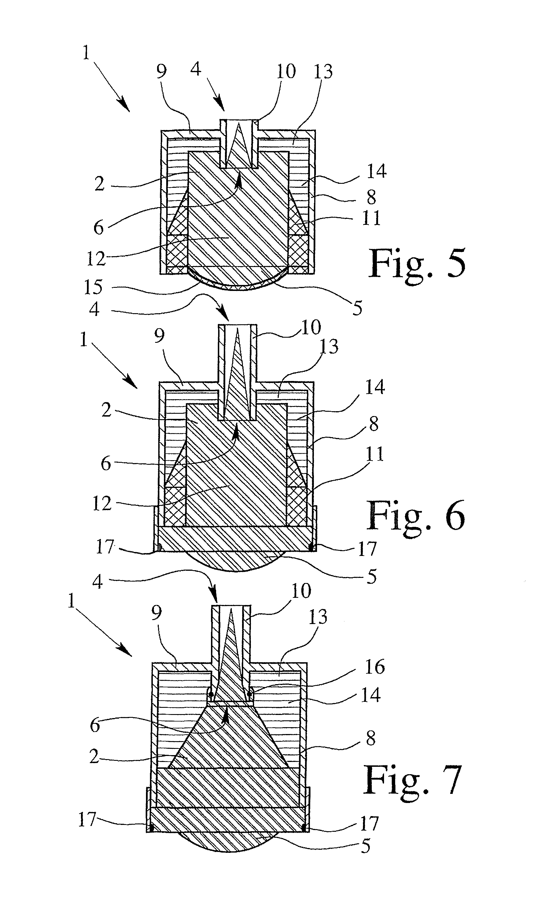
[0015]Preferably, the supply section is additionally formed by a waveguide, which is attached to the conductive sheath on the outside and at the supply opening or which is inserted in the supply opening in the conductive sheath and then preferably extends into the dielectric body. In both cases, a connection to an electromagnetic supply source can be made in a simple manner.
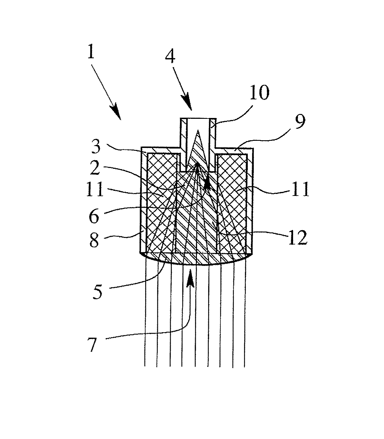
[0016]The lens-shaped radiation section in the dielectric antenna according to the invention is fundamentally disengaged so that electromagnetic waves are emitted from the radiation section having an even as possible phase front. Here, it is to be taken into consideration that in order to achieve an even phase front, the runtimes of the different parts of the electromagnetic radiation from the supply section to the different spots of the lens surface of the radiation section have to be approximately the same and that the refraction of the electromagnetic radiation resulting at the transition from the surface of the dielectric body in the radiation section to the outer space has to take place due to the dielectricity transfer between the dielectric body and the outer space in the direction of the main radiation direction, so that good directional characteristics result.
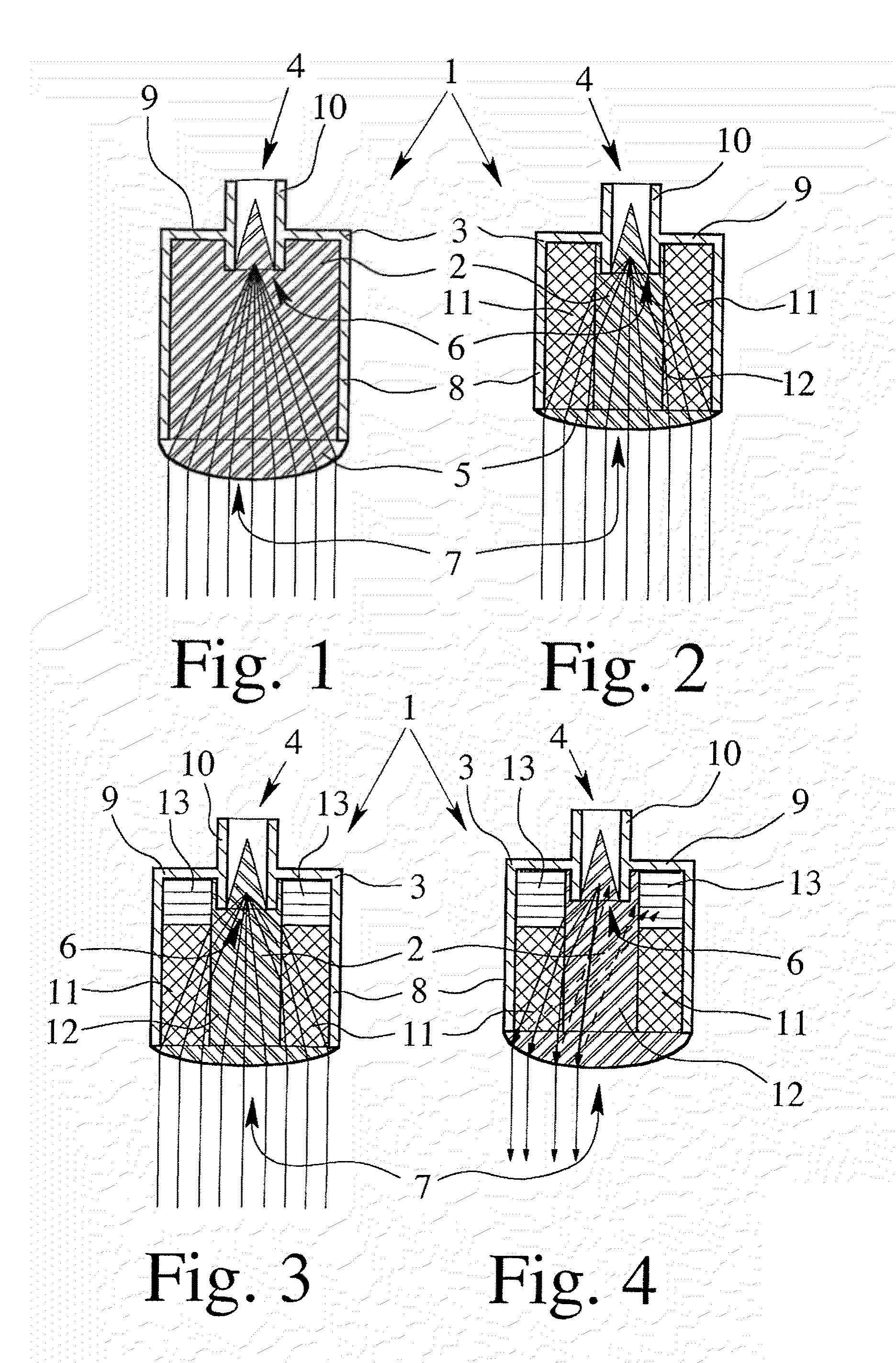
[0019]Using this measure, the electromagnetic radiation reaches the radiation area directly—without previous reflection—which previously, without the low-permittivity boundary area, struck the sidewall of the conductive sheath. Furthermore, the electromagnetic radiation hitting the boundary area of the radiation section of the dielectric body arrives at a shallower angle than is the case in dielectric bodies that consist of a uniform dielectric. For this reason, only a comparably lower correction of the radiation path is necessary by the lens-shaped radiation section, so that the lens thickness can be considerably less in total. Furthermore, the antenna can be built distinctly shorter in the main radiation direction in order to illuminate the same radiation opening and to achieve the same directional characteristics as comparably longer conventional dielectric antennae. The results of this measure are short-built dielectric antennae having very flat lens geometry.
[0021]In order to avoid losses when the electromagnetic radiation from the supply section enters into the dielectric body, the absorber layer is, in particular, adjacent to the conductive sheath and, in particular, not provided in the primary strong field area of the dielectric body. The term “primary strong field area” is used for the area that is impinged directly—i.e., without consideration of reflection—by electromagnetic radiation. Thus, it is ensured that, in the dielectric body, only reflected electromagnetic radiation—e.g., from the conductive sheath—is reflected onto the absorber layer and cannot be reflected any longer. Reflections are often not desired because they can lead to noise in the emission signal and to echoes in the emission signals to be evaluated and make the evaluation of the electromagnetic radiation emitted and received by the dielectric antenna more difficult.
[0022]In a further preferred embodiment of the invention, the dielectric body has a side absorber layer in a boundary section adjacent to the conductive sheath, which is provided, in particular, in the boundary section to the sidewall of the conductive sheath and, in particular, is not in the primary strong field area of the dielectric body. This side absorber layer makes it possible to absorb reflected and to be reflected electromagnetic radiation emitted in the direction of the sidewall of the conductive sheath and, thus, to avoid further reflection. It is of particular advantage, here, when the side absorber layer is arranged adjacent to the supply-side absorber layer in the supply section of the dielectric body. In particular, this is advantageous in view of producing such an absorber layer.

Problems solved by technology

However, these requirements are contradictory in terms of constructive measures, which normally have to be used for technical implementation.
In addition to the difficult implementation of a narrow main radiation direction and simultaneous compact configuration, known dielectric antennae have a further disadvantage, which is associated with the mutual arrangement of electromagnetic supply element—waveguide—and the dielectric body or, respectively, lens formed of dielectric material.
When it is being discussed that the conductive sheath “essentially” encloses the dielectric body from the supply section to the radiation section, then it is meant that it is not compulsory that the conductive sheath serving as a boundary of the electromagnetic radiation extends exactly to the edge of the radiation section, since possibly due to the chosen geometry of the sheath, it is not possible that electromagnetic radiation struck in the supply section reaches this end area of the dielectric body.
Both of the variations mentioned above have the disadvantage that a configuration suitable also, for example, for hygienic purposes can only be poorly implemented.
Aside from the already very challenging structural implementation of an antenna having a dielectric body at least partially enclosed by the conductive sheath, this configuration has the additional disadvantage that the conductive sheath and the dielectric body extend together up to a far preceding area of the antenna and are comparably exposed and, thus, are at risk for contamination.
In the antenna construction with the space between the electromagnetic supply element and the dielectric body, there is always the risk of contamination of the antenna surfaces that are facing the space; furthermore, excess and negative pressure applications could be a problem due to the existing space.
Furthermore, such dielectric antennae having a tapered form opening in the direction of radiation and having a tapered conductive sheath have been shown to be disadvantageous in that the production effort for such angled—but not right-angled—constructions is comparably high, so that there is interest in finding simpler and more inexpensive ways to produce antennae configurations, having at least comparable radiation characteristics to those antennae known from the prior art.

Method used


Image

  • Dielectric antenna
  • Dielectric antenna
  • Dielectric antenna

Examples


Embodiment Construction

[0040]FIG. 1 shows a first, very simple embodiment of a dielectric antenna 1 according to the invention having a dielectric body 2 and an electrically conductive sheath, wherein the dielectric body 2 can be struck by electromagnetic radiation and the electromagnetic radiation—at least partially—can be emitted from the dielectric body 2 via a lens-shaped radiation section 5. The conductive sheath 3 encompasses the dielectric body 2 from the supply section 4 to the radiation section 5. A supply opening 6 is provided in the supply section 4 of the conductive sheath 3 and a radiation opening 7 is provided in the area of the radiation section of the conductive sheath, so that the dielectric body 2 can be struck by electromagnetic radiation.

[0041]The dielectric antenna shown in FIG. 1 is characterized—as are all of the dielectric antennae shown in the other figures—in that the dielectric body 2 essentially has the cross section of the radiation opening 7 in the area of the supply section ...


PUM

PropertyMeasurementUnit
dielectricaaaaaaaaaa
areaaaaaaaaaaa
permittivityaaaaaaaaaa

Abstract

A dielectric antenna having an at least partially dielectric body and an electrically conductive sheath, wherein the dielectric body can be struck on a supply section with electromagnetic radiation and the electromagnetic radiation can be at least partially emitted from the dielectric body via a lens-shaped radiation section. The conductive sheath essentially surrounds the dielectric body from the supply section to the radiation section and a supply opening is provided in the conductive sheath in the area of the supply section and a radiation opening is provided in the conductive sheath in the area of the radiation section. The dielectric antenna that is easy to produce, has little interference and has a short construction as a result of the dielectric antenna having essentially the cross section of the radiation opening in the area of the supply section.

Description

BACKGROUND OF THE INVENTION[0001]1. Field of Invention[0002]The invention relates to a dielectric antenna having an at least partially dielectric body and an electrically conductive sheath, wherein the dielectric body can be struck with electromagnetic radiation on a supply section and the electromagnetic radiation can at least partially be emitted from the dielectric body via a lens-shaped radiation section. The conductive sheath essentially surrounds the dielectric body from the supply section to the radiation section and a supply opening is provided in the conductive sheath in the area of the supply section and a radiation opening is provided in the conductive sheath in the area of the radiation section.[0003]2. Description of Related Art[0004]Dielectric antennae are known from different fields of engineering in very different configurations. However, dielectric antennae have in common that dielectric materials are used for guiding and emitting electromagnetic waves, in particula...

Claims


Application Information

Patent Timeline
Patent Type & Authority Patents(United States)
IPC IPC(8): H01Q13/00H01Q19/06
CPCG01F23/284H01Q1/225H01Q19/08H01Q19/06H01Q13/02
Inventor GERDING, MICHAELMUSCH, THOMASPOHL, NILS
Owner KROHNE MESSTECHNICK GMBH & CO KG
Why Eureka
Try Eureka