Flexible dual skin wall and device for tensioning a dual skin flexible wall

a flexible wall and dual skin technology, applied in the field of shelters, can solve the problems of deflation and ruin of the flexible wall, particularly inconvenient water retention areas, and walls that require considerable compressed air energy,

Active Publication Date: 2012-08-21
TISSAGE & ENDUCTION SERGE FERRARI SA
View PDF55 Cites 16 Cited by
  • Summary
  • Abstract
  • Description
  • Claims
  • Application Information

AI Technical Summary

Benefits of technology

[0020]In other words, such a tensioning device is arranged at each joint of the flexible wall with a rigid mount and allows the flexible wall to connect with the rigid mount, and at the same time enables the two skins to be tensioned in a flat and symmetrical manner so as to eliminate the folds on their surfaces.
[0041]Moreover, so as to make it easier for the boltrope to slide inside the section and also guarantee a good seal of the boltrope / section joint, wires can be arranged on the surface of the boltrope and placed parallel to the cord.

Problems solved by technology

Such water-retention areas are particularly inconvenient because they cause water stains, they enable the formation of green algae and are the cause of serious leaks that may occur in the field of industrial tent roofs.
Moreover, such walls require considerable compressed-air energy since the inflated air volume is very large in order to tension the fabrics that form the skins.
Furthermore, the damage of one of the skins of the flexible roof automatically causes the deflation and ruin of the flexible wall.
Moreover, it is impossible to use skins made of an open-weave fabric because each of the skins must be impermeable to air.
Furthermore, these lenticular double skins have a very poor insulation capacity in summer and in winter due to the fact that the thickness of the lens thus formed between the two tensioned skins is in the order of 1 meter, a thickness that results in the internal air convection flows being enormous and responsible for large thermal exchanges and therefore for the loss of insulation.
However, once the sleeve is inflated, this type of device no longer allows the dual-skin wall to be moved in translation in relation to the rigid mount.
Such a device has no cord connected with the edges of the two skins and does not allow the wall to be removed once the bead has been inflated.
Lastly, with this device it is not possible to achieve an effective tensioning of the wall since, on inflating the bead, the latter may cause the groove strip to dislodge.

Method used


Image

  • Flexible dual skin wall and device for tensioning a dual skin flexible wall
  • Flexible dual skin wall and device for tensioning a dual skin flexible wall
  • Flexible dual skin wall and device for tensioning a dual skin flexible wall

Examples


first embodiment

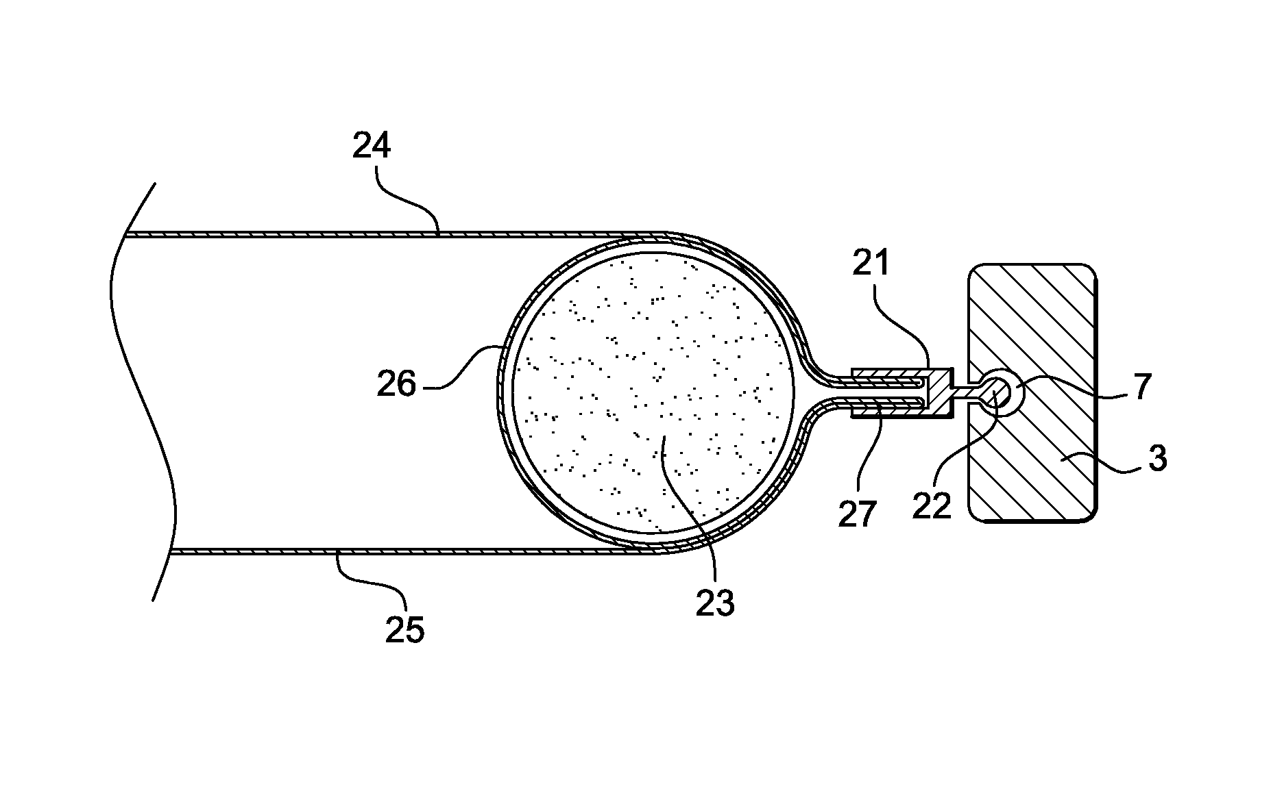
[0024]Thus, the device can be formed by an internal hem connecting the two skins, the two skins being formed by a single sheet of fabric folded over itself and forming such internal hem at one edge of the wall on which a boltrope incorporating the cord is inserted, the internal hem receiving the inflatable bead.

[0025]In other words, the dual-skin flexible wall and the tensioning device are created by folding over a sheet of fabric on itself and incorporating an inflatable bead in an internal hem enclosed by means of a boltrope incorporating the cord. Only the internal hem is inflated by means of the bead and only the bead needs to be made of a gas-tight material.

second embodiment

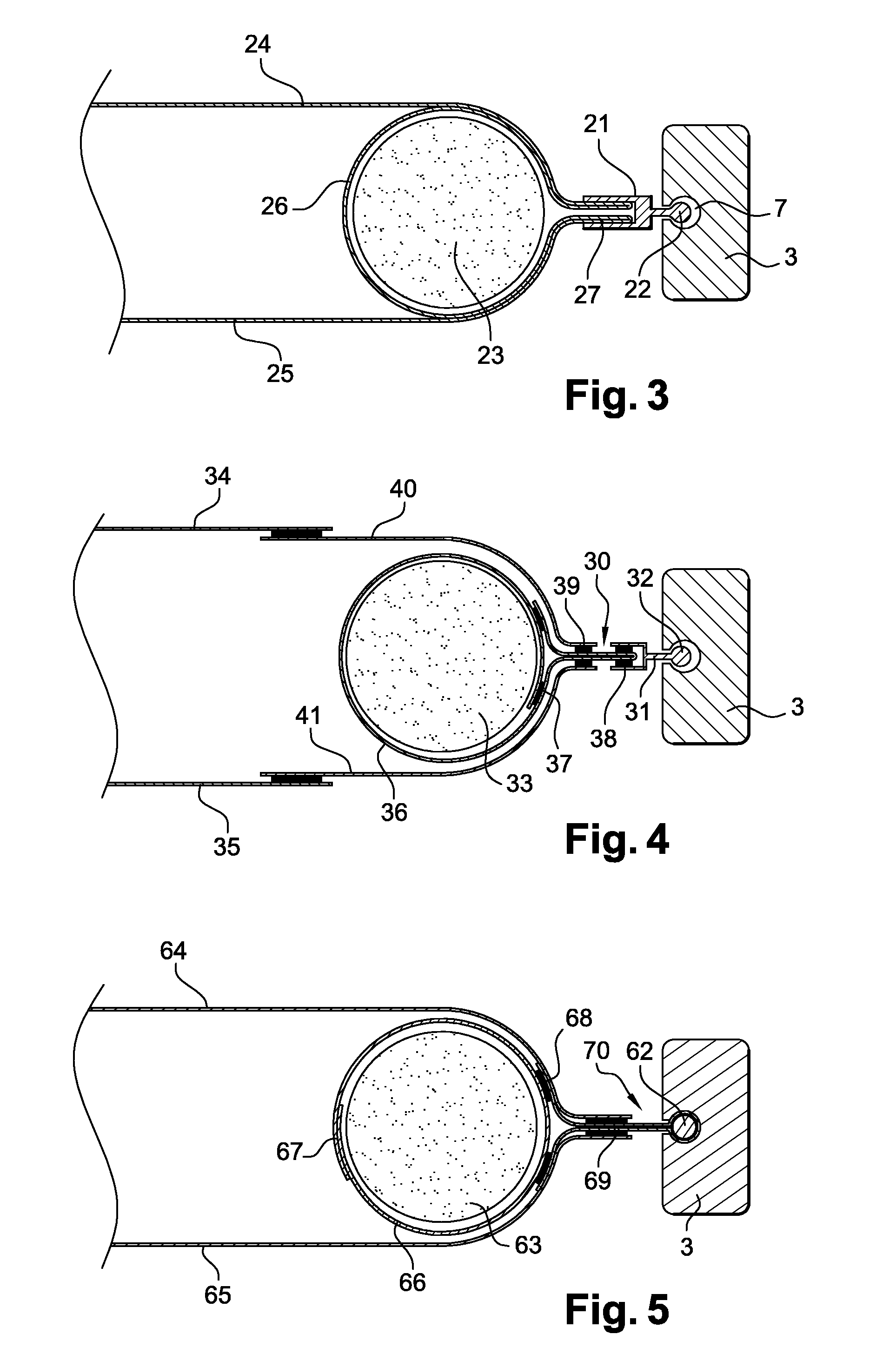
[0026] the device may be formed by a first band folded over itself and forming an internal pocket, the internal pocket being positioned at one of the edges of the wall on which a boltrope incorporating the cord is inserted, the internal pocket receiving the inflatable bead.

[0027]In this case, the two skins may be directly or indirectly connected with the internal pocket or with the boltrope. Moreover, each of the skins may be made of different materials, which can be particularly advantageous when one of the skins is made of a very expensive technical material. It is therefore not necessary to use the material used for the skins to form, on the one hand, the first band and, on the other hand, the two coupling bands inserted on the band folded over on itself.

[0028]Similarly, the boltrope may itself be welded to the band folded over on itself in a flat or curved portion of the band once inflated by the bead.

[0029]Advantageously, the device may have a quick-coupling device positioned b...


PUM


Abstract

A device for tensioning a dual-skin flexible wall capable of interaction with at least one rigid mount, the device being mounted at the opposite edges of two skins to be retained by the rigid mount. The device includes a cord designed to interact with a groove formed in the rigid mount, and an inflatable bead capable of spacing the two skins away from and parallel to each other. Once inflated, the inflatable bead has a substantially cylindrical shape and remains confined outside the volume occupied by the rigid mount.

Description

CROSS REFERENCED TO RELATED APPLICATIONS[0001]This application is a National Stage filing under 35. U.S.C. §371 of PCT Application No. PCT / FR2008 / 051446, filed on Jul. 31, 2008. This application also claims the benefit of French Application No. 0705623 filed on Aug. 1, 2007. The entirety of each application is incorporated herein by reference.FIELD OF THE INVENTION[0002]The invention relates to the field of shelters erected from rigid, usually metallic, mounts and fabric dual-skin walls extending between two parallel rigid mounts. These dual-skin walls, designed to form shelters, may notably take the form of coverings serving as a roof, of walls, of internal partitions or of ceilings.[0003]The invention concerns more particularly the device for tensioning such a dual-skin flexible wall with the metallic structure formed by the various rigid mounts. The invention also concerns the flexible wall equipped with such a tensioning device.BACKGROUND OF THE INVENTION[0004]The use of compres...

Claims


Application Information

Patent Timeline
Patent Type & Authority Patents(United States)
IPC IPC(8): E04G5/12E04B7/14
CPCA01G9/1415E04H15/20Y02A40/25
Inventor SAIZ, CARLOSBARIL, SEBASTIEN
Owner TISSAGE & ENDUCTION SERGE FERRARI SA
Why Eureka
Try Eureka