A Laminar Flow Cooling Control Method for a Stepped Hot Strip Steel Production Line

A technology of laminar flow cooling and control method, applied in the direction of temperature control, etc., can solve the problems of difficulty in large-scale and stable production of hot continuous rolling, and achieve the effects of strong practicability, good coil shape and easy operation.

Active Publication Date: 2016-06-29
武汉钢铁有限公司
View PDF6 Cites 0 Cited by
  • Summary
  • Abstract
  • Description
  • Claims
  • Application Information

AI Technical Summary

Problems solved by technology
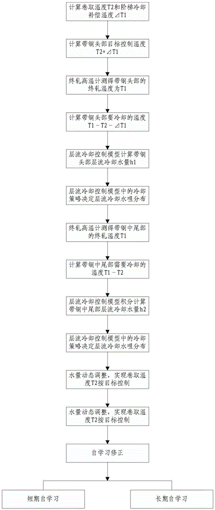
However, for the production of thin materials with a thickness of less than 2.0mm, due to the characteristics of high strip threading speed, high precision requirements for rolled pieces and equipment, it is difficult to achieve large-scale and stable production in conventional hot continuous rolling

Method used


Image

  • A Laminar Flow Cooling Control Method for a Stepped Hot Strip Steel Production Line
  • A Laminar Flow Cooling Control Method for a Stepped Hot Strip Steel Production Line
  • A Laminar Flow Cooling Control Method for a Stepped Hot Strip Steel Production Line

Examples


Embodiment 1

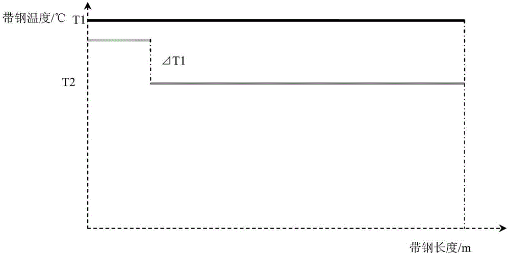
[0033] Steel type: SPHC, thickness 1.2mm, coiling temperature 660°C, step cooling compensation temperature -10°C, according to figure 2 The step cooling compensation temperature shown in above is executed, and the calculation starts at the head of the strip. The temperature is controlled at 650°C from 0 to 5m, and the target coiling temperature is controlled at 660°C after 5m. During the production process, the strip does not turn over on the roller table. Heaping and stacking of steel. After the strip steel is coiled, the inner ring of the steel coil does not have the head folding and the inner ring of the steel coil unwinding.

Embodiment 2

[0035] Steel type: SPHC, thickness 1.8mm, coiling temperature 640°C, step cooling compensation temperature -10°C, according to figure 2 The step cooling compensation temperature shown in above is executed, the strip head starts to be calculated, the temperature is controlled at 630°C at 0~1m, and the target coiling temperature is controlled at 640°C after 5m, during the production process, the strip does not turn over on the roller table Heaping and stacking of steel. After the strip steel is coiled, the inner ring of the steel coil does not have the head folding and the inner ring of the steel coil unwinding.

Embodiment 3

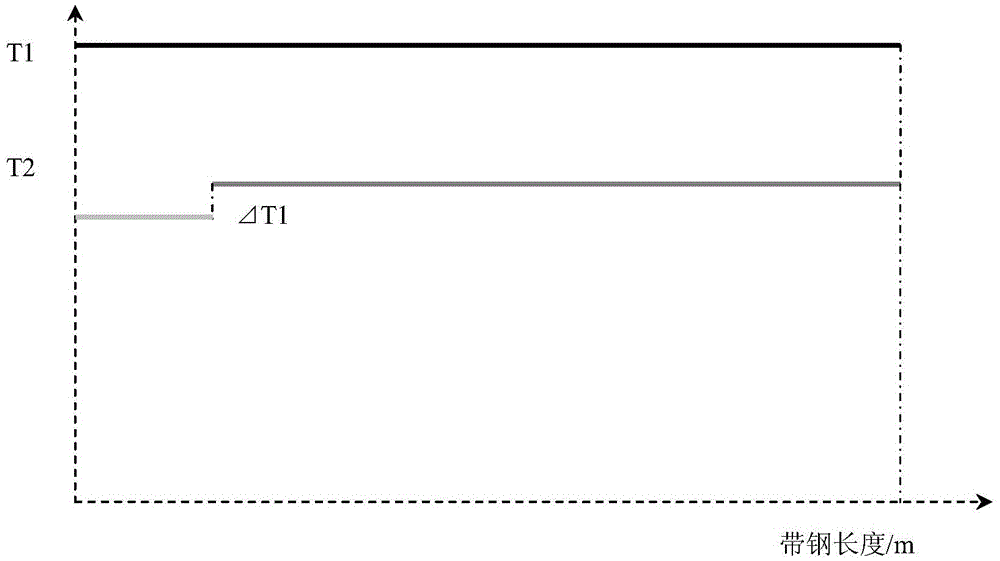
[0037] Steel type: Q215, thickness 1.1mm, coiling temperature 600°C, step cooling compensation temperature +50°C, press image 3 The step cooling compensation temperature shown in the above is executed, and the calculation starts at the head of the strip. The temperature is controlled at 650°C from 0 to 10m, and the target coiling temperature is controlled at 600°C after 10m. From the beginning, there is no phenomenon of stacking steel, and the inner ring of the steel coil does not have the head folding and the inner ring of the steel coil after the strip steel is coiled.


PUM


Abstract

The invention discloses a stepped hot rolled strip production line laminar flow cooling control method. The method comprises the following steps: I, setting the temperature of the head of strip steel: calculating temperature to be cooled of the head of the strip steel by a laminar flow cooling control model through rolling temperature, stepped cooling compensation temperature and strip steel head finish rolling temperature; II, setting a strip steel head cooling scheme: calculating cooling water quantity of the laminar flow of the head of the strip steel by the laminar flow cooling control model according to the temperature to be cooled of the head of the strip steel and the speed of the strip steel, and then determining the cooling water nozzle distribution of the laminar flow according to a cooling strategy in the laminar flow cooling control model; III, setting the temperature of the tail part in the strip steel: calculating the temperature to be cooled of the tail part in the strip steel by the laminar flow cooling control model through the finish rolling temperature of the tail part in the strip steel; IV, setting the cooling scheme of the tail part in the strip steel. The method has the characteristics that the turn-up of the head of the strip steel on a track is prevented and folding and unwinding are prevented from occurring on the inner ring of a steel coil, and can be widely applied to the field of production of hot rolled strips.

Description

technical field [0001] The invention relates to the field of hot-rolled steel strip production, in particular to a laminar flow cooling control method for a stepped hot-rolled strip steel production line. Background technique [0002] With the development of hot rolling technology and the competition in the steel market, "replacing heat with cold" thin material rolling has become one of the main directions for the development of hot rolling. This is because thin slab continuous casting and rolling has inherent advantages in the production of thin products: uniform temperature of the rolled piece and high rolling stability, therefore, it has the ability to produce thin strip steel on a large scale. However, for the production of thin products with a thickness of less than 2.0mm, due to the characteristics of high strip threading speed, high precision requirements for rolled pieces and equipment, it is difficult to achieve large-scale and stable production in conventional hot ...

Claims


Application Information

Patent Timeline
Patent Type & Authority Patents(China)
IPC IPC(8): B21B37/76
CPCB21B37/76
Inventor 田军利陈良陈宏涛张帆高智李宇兴刘刚
Owner 武汉钢铁有限公司
Why Eureka
Try Eureka