Decorative finger adornment and method of making same

a finger adornment and decorative technology, applied in the field of decorative ringlike structures, can solve the problems of insufficient pattern variety, inability to wear metal jewelry, ring structure and form are typically lacking, etc., and achieve the effects of avoiding creases or folds in the fabric, and reducing the risk of injury

Inactive Publication Date: 2011-10-27
WEBER KRISTA L
View PDF11 Cites 0 Cited by
  • Summary
  • Abstract
  • Description
  • Claims
  • Application Information

AI Technical Summary

Benefits of technology

[0007]The structure of the compressed fabric strip is then folded so that the opposing ends of the strip are adjoined with one another to form a ring. The fabric ring is then heated with a cylindrical iron which reheats the rigid member causing the fabric ring to take on the fixed shape of a ring and eliminating any creases or folds in the fabric. The fabric ring then undergoes a cooling period allowing the rigid material to harden and provide the fabric ring with fixed shape, durability and flexibility.

Problems solved by technology

While most people enjoy wearing rings either for style or to commemorate an accomplishment, many people are allergic to metals commonly used in jewelry and are thus unable to wear metal jewelry.
There are but a few alternatives presently available to such people such as leather bands which are heavy, stiff and often require metal riveting which does not avoid the allergy.
It is also known to use rubber or string, but these rings are thin and do not provide sufficient variety in patterns and are often monochromatic.
Decorative fabric ring-like structures are also known, however, such decorative fabric rings typically lack structure and form, easily become frayed, and do not maintain shape and consistency.

Method used


Image

  • Decorative finger adornment and method of making same
  • Decorative finger adornment and method of making same
  • Decorative finger adornment and method of making same

Examples


Embodiment Construction

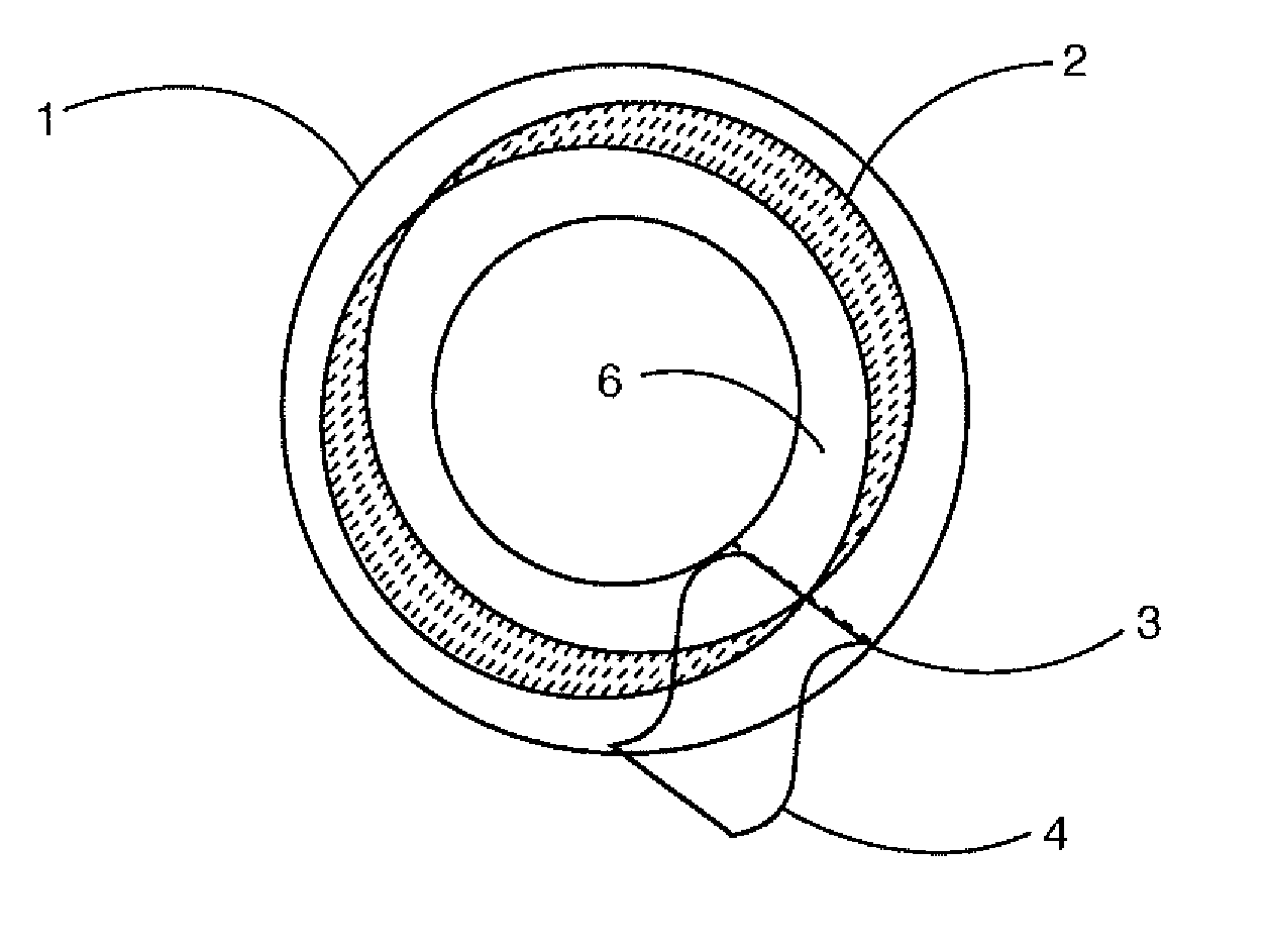
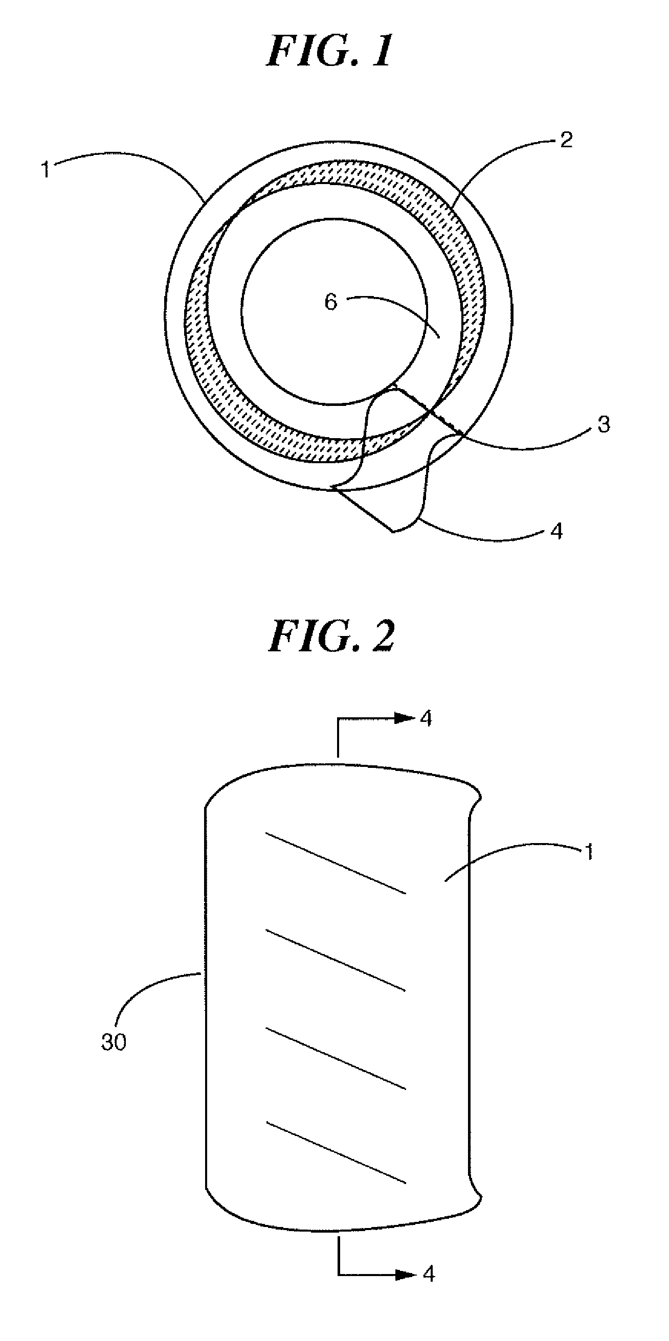
[0015]With reference to the drawings, FIG. 1 shows a generally cylindrical decorative fabric ring. Various styles of fabric can be used to create the fabric ring to provide a highly decorative and pleasing appearance.

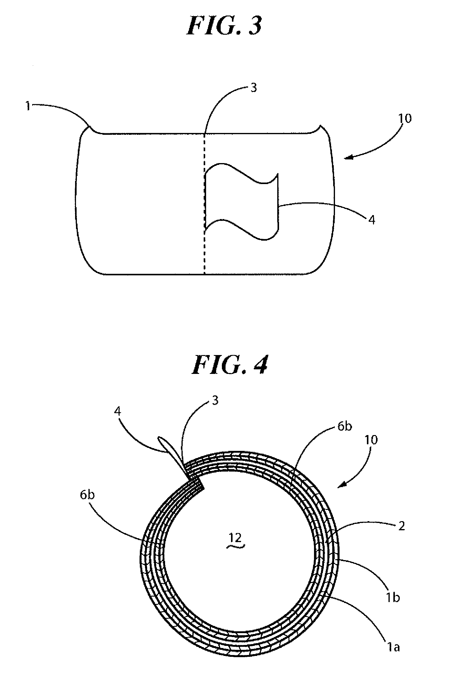
[0016]Referring now to the invention in more detail, FIG. 1 schematically shows a fabric ring constructed in accordance with the present invention and which includes an internal strip of rigid material 2 that is used to provide structure to the ring and bond the folded fabric to create a compressed fabric strip. The shown fabric ring 10 consists of an outer fabric layer 1 and an inner fabric layer 6, which layers make up the outer and inner portion of a compressed fabric strip. Opposite ends of the compressed fabric strip are affixed to each other creating a seam 3. The ends of the fabric strip that create the seam 3 of the compressed fabric strip are in a preferred, nonlimiting embodiment sewn together because this method of attachment results in a more durable fabric ...


PUM

PropertyMeasurementUnit
widthaaaaaaaaaa
durabilityaaaaaaaaaa
flexibilityaaaaaaaaaa

Abstract

A ring comprising a first fabric layer; a second fabric layer circumscribing the first fabric layer and a rigid member disposed between the first fabric layer and the second fabric layer. The ring being manufactured by providing a sheet of fabric, folding a first panel about a fold line towards a center of the sheet and folding a second panel along a second fold line towards the sheet such that the first panel and second panel are in abutting relationship once folded to create a seam. A rigid member is placed along the seam. The panel is folded about the seam so as to sandwich the rigid member between the first panel and second panel. Heat is applied to the entire structure to bond the first panel to the second panel. A first end of the panel is affixed to a second end of the panel to form a ring. The ring is placed about a hot cylindrical surface and then removed to harden.

Description

CROSS-REFERENCE TO RELATED APPLICATION[0001]This application claims priority to U.S. Provisional patent Application No. 61 / 343,183 filed Apr. 26, 2010, in the entirety hereby incorporated by reference.BACKGROUND OF THE INVENTION[0002]The present invention relates to decorative ring-like structures, and more particularly, to a method of fabricating decorative non-metallic ring-like structures using various materials which materials give the ring-like structure fixed shape, durability, and flexibility.[0003]While most people enjoy wearing rings either for style or to commemorate an accomplishment, many people are allergic to metals commonly used in jewelry and are thus unable to wear metal jewelry. There are but a few alternatives presently available to such people such as leather bands which are heavy, stiff and often require metal riveting which does not avoid the allergy. It is also known to use rubber or string, but these rings are thin and do not provide sufficient variety in pat...

Claims


Application Information

Patent Timeline
Patent Type & Authority Applications(United States)
IPC IPC(8): A44C9/00B32B38/00B32B37/12B32B37/14B32B37/02B32B37/06
CPCA44C9/0007Y10T156/1036A44C27/00A44C9/0015
Inventor WEBER, KRISTA L.
Owner WEBER KRISTA L
Why Eureka
Try Eureka