

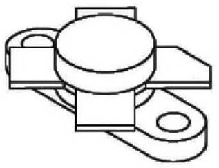
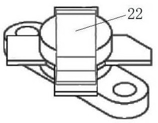
Workpiece profiling device
A technology of workpiece and feeding device, applied in the direction of feeding device, positioning device, storage device, etc., can solve the problems of low manual deformation efficiency and poor deformation consistency, and achieve smooth and smooth appearance of workpiece, improved consistency, and high production efficiency. Effect
- Summary
- Abstract
- Description
- Claims
- Application Information
AI Technical Summary
Problems solved by technology
Method used
Image

Examples
Embodiment Construction
[0027] The present invention will be further explained below in conjunction with the accompanying drawings and embodiments.
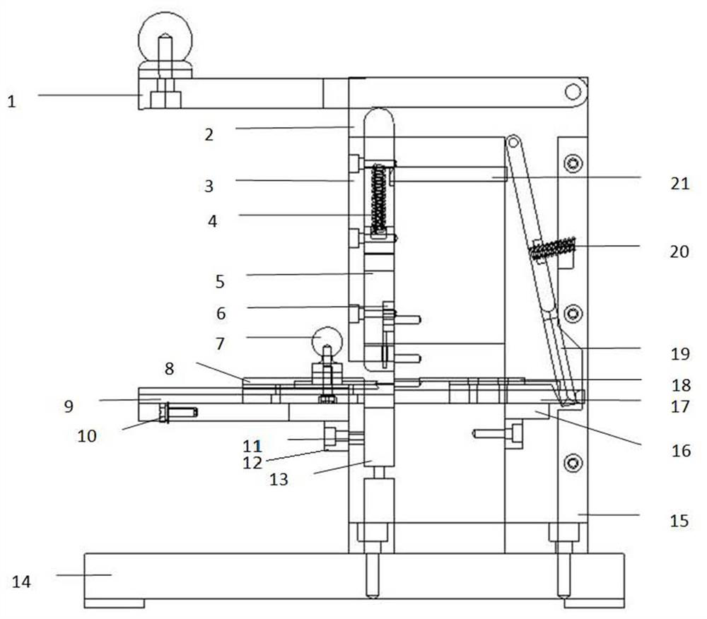
[0028] The invention relates to a workpiece pressing device, which includes a feeding device, a punching device and an ejecting device. The shielding strip enters the stamping device through the feeding device, and after being moved out of the feeding device, the stamping device is pressed to deform the shielding strip. After the shielding strip produces expected deformation, the ejection device ejects the shielding strip. Such as Figure 3-6 As shown, it includes pressing rod 1, bracket 2, cover plate 3, first spring 4, stamping rod 5, ejector rod 6, feeding rack push rod 7, feeding rack 8, feeding rack base 9, feeding rack Frame limit column 10, adjusting top wire 11, loading rack bracket 12, lower cushion block 13, base 14, back panel 15, limit support block 16, feeding slider 17, feeding sheet 18, swing rod 19. The second spring 20, the slider 21,...
PUM
 Abstract
Description
Claims
Application Information