Device of a rotationally fixedly connecting a shaft to a component which is rotatably mounted on the shaft

a technology of rotating fixed connection and component, which is applied in the direction of interengaging clutches, friction clutches, clutches, etc., can solve the problems of high manufacturing cost, unsatisfactory large amount of installation space, and impair the overall efficiency of the transmission device, and achieve low installation space requirements, high degree of driving comfort, and cost-efficient manufacturing

Active Publication Date: 2012-08-21
ZF FRIEDRICHSHAFEN AG
View PDF28 Cites 2 Cited by
  • Summary
  • Abstract
  • Description
  • Claims
  • Application Information

AI Technical Summary

Benefits of technology

[0008]It is therefore an object of the invention to make available a device for connecting a shaft in a rotationally fixed manner to a component rotatably mounted on the shaft, which is characterized by a low installation space requirement, can be cost-efficiently manufactured, and by means of which a high degree of driving comfort and simultaneously low component stress can be achieved.
[0009]With the device according to the invention for rotationally fixing a shaft to a component that is rotatably mounted on the shaft, preferably for connecting a gearwheel designed as a loose wheel of a gear stage of a transmission device to a transmission shaft with an actuating element displaceable in axial direction and rotatably mounted on the shaft, which can be rotationally fixed to the shaft via an actuator and which makes possible bringing the actuating element in operative connection with the component in a frictionally engaging manner in the rotationally fixed state by actuating the corresponding actuator, and with which a rotational speed difference between the component and the shaft can be at least approximately compensated for by means of the actuating element that can be actuated on the actuator side, the actuating element for rotationally fixing the component to the shaft by means of the actuator can be transferred from a rotationally fixed state into a state in which it can be rotated relative to the shaft and is operatively connected to at least one support body in such a way that the component, in the state in which the actuating element can be rotated relative to the shaft, can be acted on by the actuating element with an actuating force that is dependent on a torque to be transmitted from the shaft to the component, and which is independent of the actuation of the actuator.
[0011]During a second phase that follows the first phase, the self-energizing mechanism is activated by transferring the actuating element from a rotationally fixed state into a state in which it can be rotated relative to the shaft and is acted on by a contact force that is dependent on the torque to be transmitted from the shaft to the component and is independent from the actuation by the actuator of the actuating element. In this way, the component is rotationally fixed to the shaft without having to supply a holding force by the actuator when a predefined threshold value of the contact force is exceeded.

Problems solved by technology

These kinds of synchronization mechanisms disadvantageously require an undesirably large amount of installation space due to their design, which incorporates friction elements, blocking devices, and claws, and are characterized by high manufacturing costs.
However, this holding force, which has to be permanently applied, impairs the overall efficiency of a transmission device.
However, this has the disadvantage that the connection between a component rotatably mounted on a shaft and the shaft itself is produced in a positive-locking manner, so that coupling the component to the shaft is not problematic regarding the driving comfort when there are low rotational speed differences between the component, or, as the case may be, a loose wheel, and a shaft.
If a connection, or, as the case may be, a rotationally fixed connection of the component to the shaft is necessary at high rotational speed differences between the component and the shaft, the positive-locking connection between the shaft and the component to be established through self-energizing, can lead to an impulse exchange with high torque peaks due to very brief response times, which results in an impairment of the driving comfort and undesirably high component stress.

Method used


Image

  • Device of a rotationally fixedly connecting a shaft to a component which is rotatably mounted on the shaft
  • Device of a rotationally fixedly connecting a shaft to a component which is rotatably mounted on the shaft
  • Device of a rotationally fixedly connecting a shaft to a component which is rotatably mounted on the shaft

Examples


Embodiment Construction

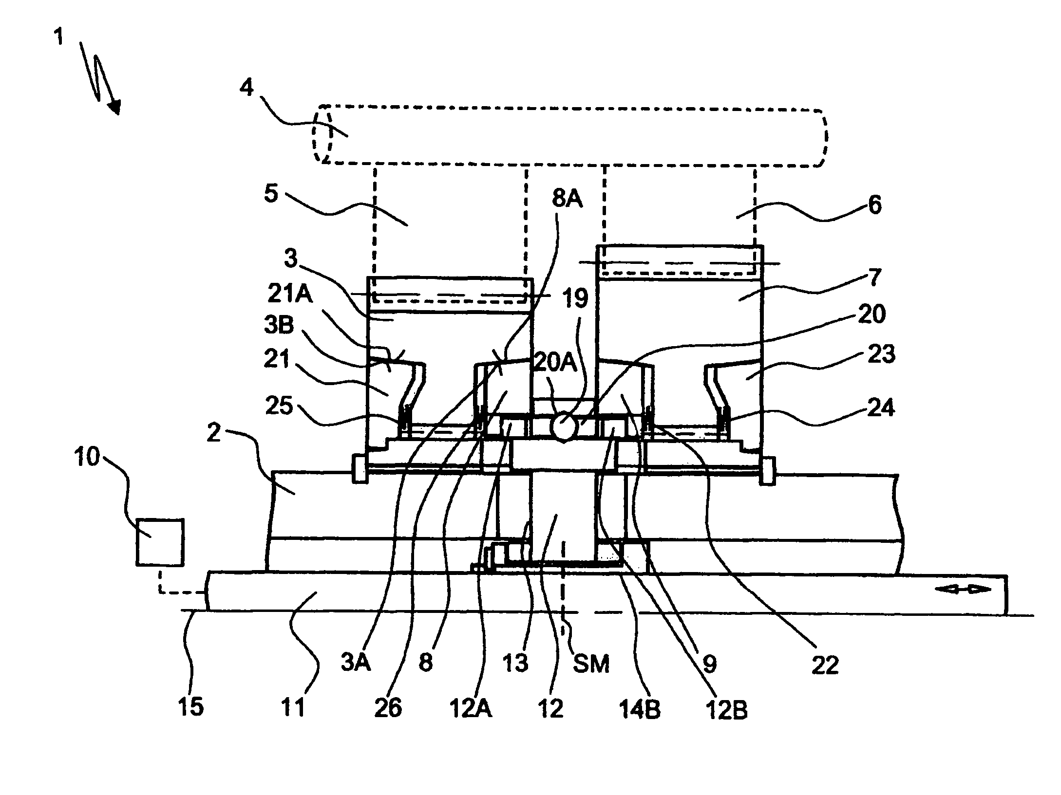
[0019]FIG. 1 shows a device 1 for connecting a shaft 2 in a rotationally fixed manner to a component 3 rotatably mounted on the shaft 2, wherein the shaft 2 is designed as a countershaft of a countershaft transmission, on which the component 3 is arranged as a loose wheel.

[0020]As a variation of this, the device 1 can also be used in other transmission devices, such as automatic transmissions, double clutch transmissions, or planetary transmissions, as a synchronizing and shifting element for automatic actuation of a transmission device during gear shifting and the like.

[0021]A transmission main shaft 4, on which a plurality of gearwheels 5, 6 designed as fixed gears are arranged, is provided parallel to the countershaft 2, wherein the gearwheel 5 meshes with the loose wheel 3 and the toothed wheel 6 with an additional loose wheel 7 rotatably mounted on the countershaft 2.

[0022]The two loose wheels 3 and 7 can be actuated alternately by the device 1 in such a way that the loose whee...


PUM


Abstract

A device for rotationally fixing a shaft to a component that is rotatably arranged on the shaft. The actuating element positively engages the components to rotationally fix the components to the shaft. The difference in rotational speeds, between the component and the shaft, can be at least approximately compensated for by the actuating element. The actuating element, for rotationally fixing the component to the shaft by the actuator, is operatively connected to at least one support body, which is rotationally fixed with respect to the shaft in such a manner that the actuating element can act upon the component with an actuating force that depends on the torque to be transmitted from the shaft to the component and which is independent of the actuation of the actuator in the state in which the actuating element can be rotated relative to the shaft.

Description

[0001]This application is a National Stage completion of PCT / EP2007 / 060458 filed Oct. 2, 2007, which claims priority from German patent application serial no. 10 2006 049 276.5 filed Oct. 19, 2006.FIELD OF THE INVENTION[0002]The invention relates to a device for rotationally fixing a shaft to a component rotationally mounted on the shaft.BACKGROUND OF THE INVENTION[0003]In transmission technology, gearwheels designed as loose wheels of various gear stages of a transmission device are connected in a rotationally fixed manner to a transmission shaft on which the loose wheels are arranged by means of so-called synchronization mechanisms. This means that when shifting a gear of a transmission device, differences in rotational speed between a loose wheel, that is to be connected, and a transmission shaft, assigned to this loose wheel, are compensated for by means of a frictionally engaging synchronization mechanism. When the loose wheel and the transmission shaft have reached the same sp...

Claims


Application Information

Patent Timeline
Patent Type & Authority Patents(United States)
IPC IPC(8): F16D23/06
CPCF16D23/04F16D2023/0618F16D2023/065F16D2023/0662
Inventor REISCH, MATTHIASMOHR, MARK
Owner ZF FRIEDRICHSHAFEN AG
Why Eureka
Try Eureka