
Packing structure

a packing structure and packaging technology, applied in the field of packaging structure, can solve the problems of increasing production costs, requiring more waste disposal space, and difficult to be detached, and achieve the effect of improving the convenience of assembling and dismantling the packing structure, and reducing the impact of external forces

Active Publication Date: 2012-08-28
AU OPTRONICS CORP
View PDF19 Cites 20 Cited by
  • Summary
  • Abstract
  • Description
  • Claims
  • Application Information

AI Technical Summary

Benefits of technology

"The present invention provides a packing structure that can be easily disassembled, with a cushion portion reliably positioned. The packing structure includes a housing and a cushion portion. A groove and a jaw portion are formed on an end portion of the cushion portion. A first tongue plate is formed on the side wall of the housing, which enters the groove through an opening of the groove and interferes with the cushion portion to limit its displacement. The packing structure also includes an outer container for providing protection to display panels or other items. The technical effects of the invention include easy assembly and disassembly, reliable positioning of the cushion portion, and efficient protection of display panels or other items."

Problems solved by technology

Packing fragile items has always been one of the important issues in transporting goods.
Poor packing may often cause the items to be damaged and therefore increase the production costs.
Especially stresses may concentrate on fragile items with special size and shape such as liquid crystal glass or display panels and damage the items.
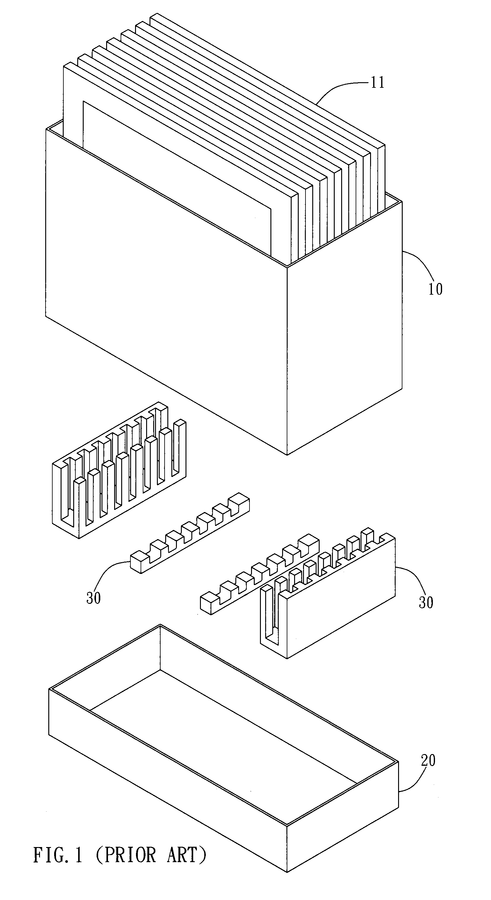
However, the cushion portion 30 adhered to the inner box 20 is not easy to be detached from the inner box 20 and thus requires greater waste disposal space.
Furthermore, due to the fact that the cushion portion 30 is not easy to be detached, the cushion portion 30 becomes waste that cannot be recycled resulting in environmental problems.

Method used


Image

  • Packing structure
  • Packing structure
  • Packing structure

Examples


Embodiment Construction

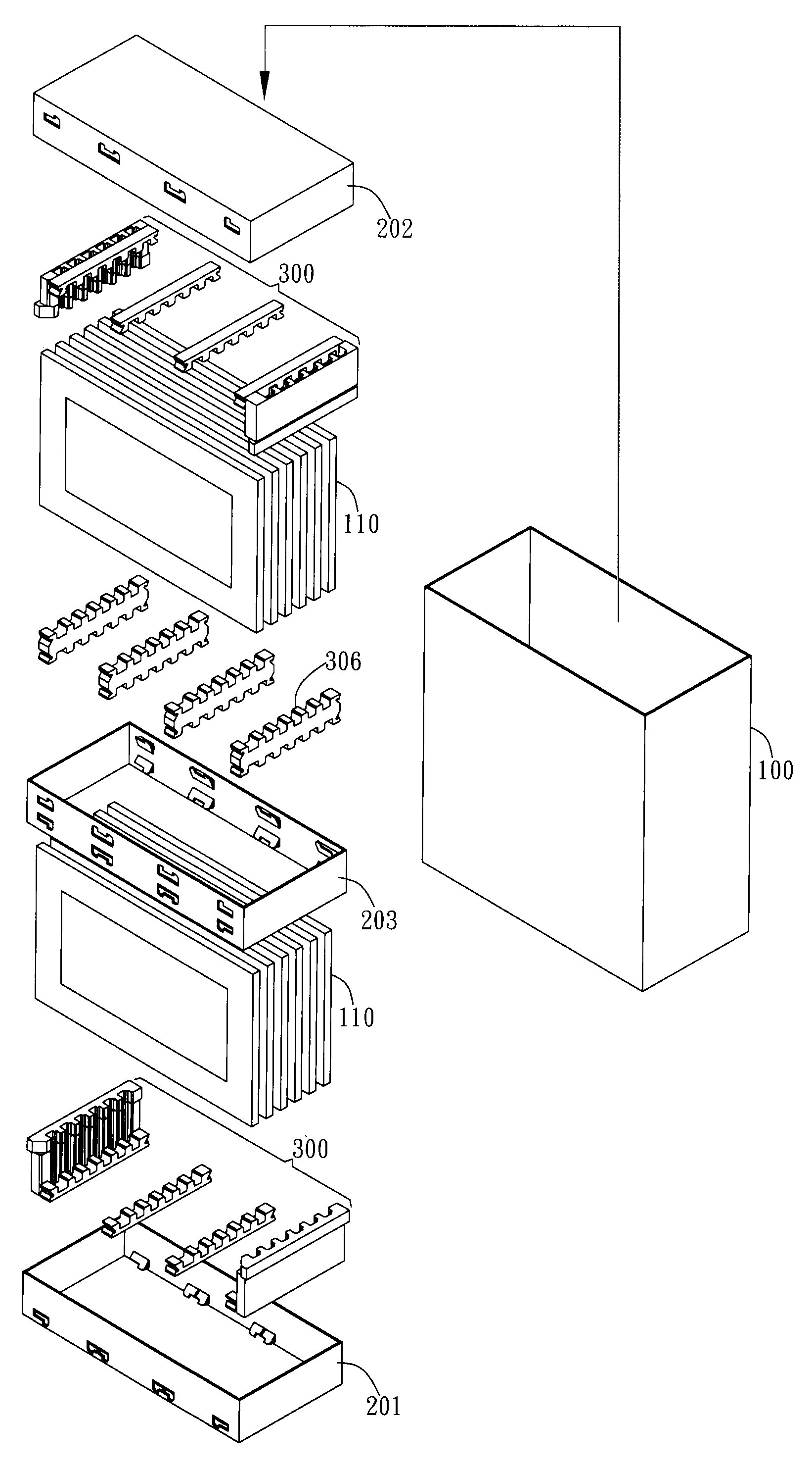
[0030]The present invention provides a packing structure preferably used in packing box structure. However, in different embodiments, the packing structure of the present invention can be used as a single cushioning packing material. In a preferred embodiment, the packing structure of the present invention is used to pack fragile plate-like items such as liquid crystal glass, display panel or general glass. However, in different embodiments, the packing structure of the present invention can be used to pack fragile items in other shapes.

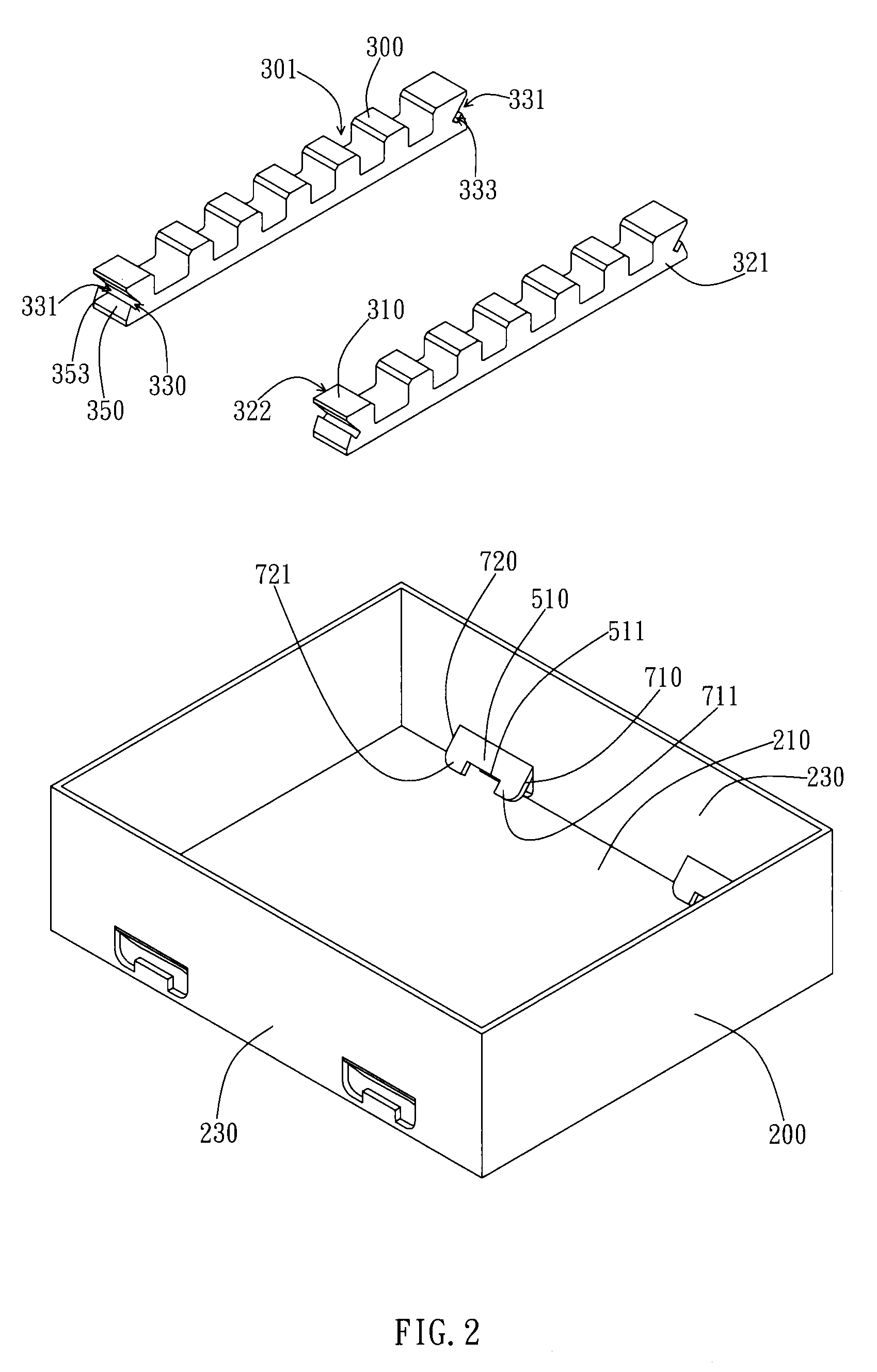
[0031]In the embodiment illustrated in FIG. 2, the packing structure includes a housing 200 and a cushion portion 300. The housing 200 includes a bottom plate 210 and a sidewall 230, wherein the sidewall 230 is connected to the bottom plate to include an angle. In the present embodiment, the sidewall 230 bends at one end of the bottom plate 210 and extends upward to be perpendicular to the bottom plate 210. Furthermore, the housing 200 is preferably ...


PUM

PropertyMeasurementUnit
anglesaaaaaaaaaa
anglesaaaaaaaaaa
anglesaaaaaaaaaa

Abstract

A packing structure includes a housing and a cushion portion. The housing includes a bottom plate and a sidewall while the cushion portion is disposed on the bottom plate of the housing. A groove and a jaw portion are formed on an end portion of the cushion portion. The jaw portion is located on a side of the groove facing the sidewall and extends away from the bottom plate. A first tongue plate is formed on the sidewall of the housing and bends inward. A free end of the first tongue plate enters the groove through an opening of the groove, wherein a backside of the jaw portion interferes with the first tongue plate to restrict the first tongue plate from leaving the groove. When the cushion portion is under external forces and moves away from the bottom plate, the first tongue plate will support a bottom inner surface within the groove to restrict a displacement of the cushion portion away from the bottom plate.

Description

BACKGROUND OF THE INVENTION[0001]1. Field of the Invention[0002]This invention relates to a packing structure; specifically, the present invention relates to packing structures for containing display panel or other fragile items and can be easily disassembled.[0003]2. Description of the Prior Art[0004]Packing fragile items has always been one of the important issues in transporting goods. Poor packing may often cause the items to be damaged and therefore increase the production costs. Especially stresses may concentrate on fragile items with special size and shape such as liquid crystal glass or display panels and damage the items.[0005]Conventionally, when transporting the display panels, normally the box to be transported will contain shock absorbing material such as Styrofoam to reduce the direct impact of external forces on the display panel. As FIG. 1 shows, the conventional packing structure includes an outer box 10, an inner box 20 and a cushion portion 30. The cushion portio...

Claims


Application Information

Patent Timeline
Patent Type & Authority Patents(United States)
IPC IPC(8): B65D81/02B65D81/107
CPCB65D5/5088B65D25/103B65D25/107B65D81/053B65D85/48B65D81/055B65D2581/058
Inventor TING, CHUNG-KUANCHEN, SHIH-CHI
Owner AU OPTRONICS CORP
Learn More