Pressurized water container

a technology for water containers and pressure vessels, applied in the direction of hose connections, screws, drawing-off water installations, etc., can solve the problem that single persons are difficult to close the closure properly

Active Publication Date: 2012-08-28
OASE GMBH
View PDF13 Cites 1 Cited by
  • Summary
  • Abstract
  • Description
  • Claims
  • Application Information

AI Technical Summary

Benefits of technology

[0004]By providing on the container parts projections and recesses matched to the projections which projections and recesses are arranged such that they secure the housing parts on one another when they are displaced relative to one another, the initiation of this displacement movement provides for a safe closure of the container even by a single person. Preferably, several projections and matching recesses should be provided on the housing parts and should preferably extend along the circumference of the container. A connection by means of at least three projections and recesses each that are uniformly distributed, i.e., arranged at a spacing of approximately 120 degrees relative to one another, can already provide a uniform sealing action. However by providing more than four projections and recesses, the canting tendency is further reduced and closing of the container becomes increasingly easier.

Problems solved by technology

These closures are difficult to close properly by a single person.
When it is not possible to uniformly maintain the tension during the closing action on all container sides, canting occurs and this leads to a connection that is not seal-tight.

Method used


Image

  • Pressurized water container
  • Pressurized water container
  • Pressurized water container

Examples


Embodiment Construction

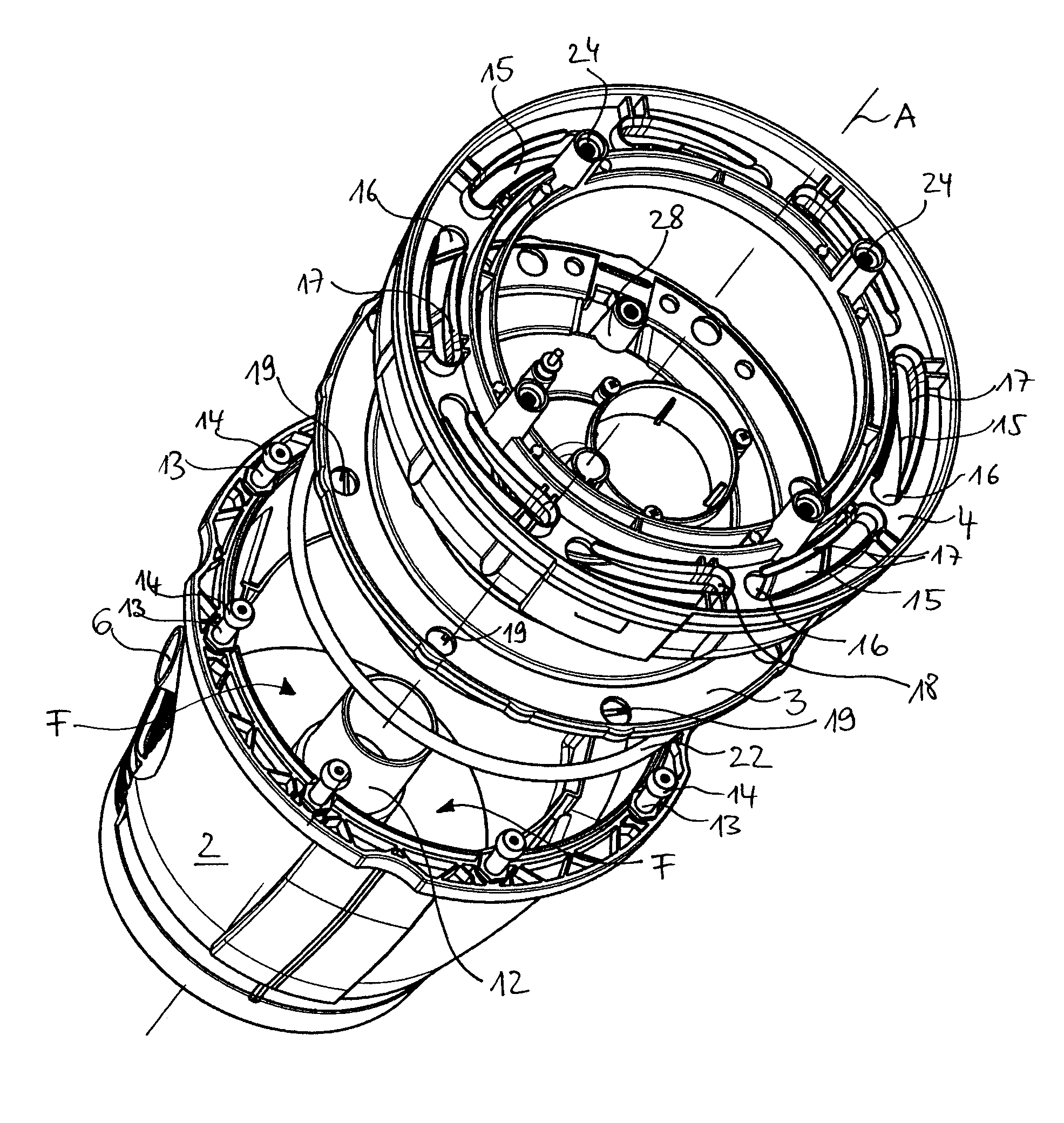
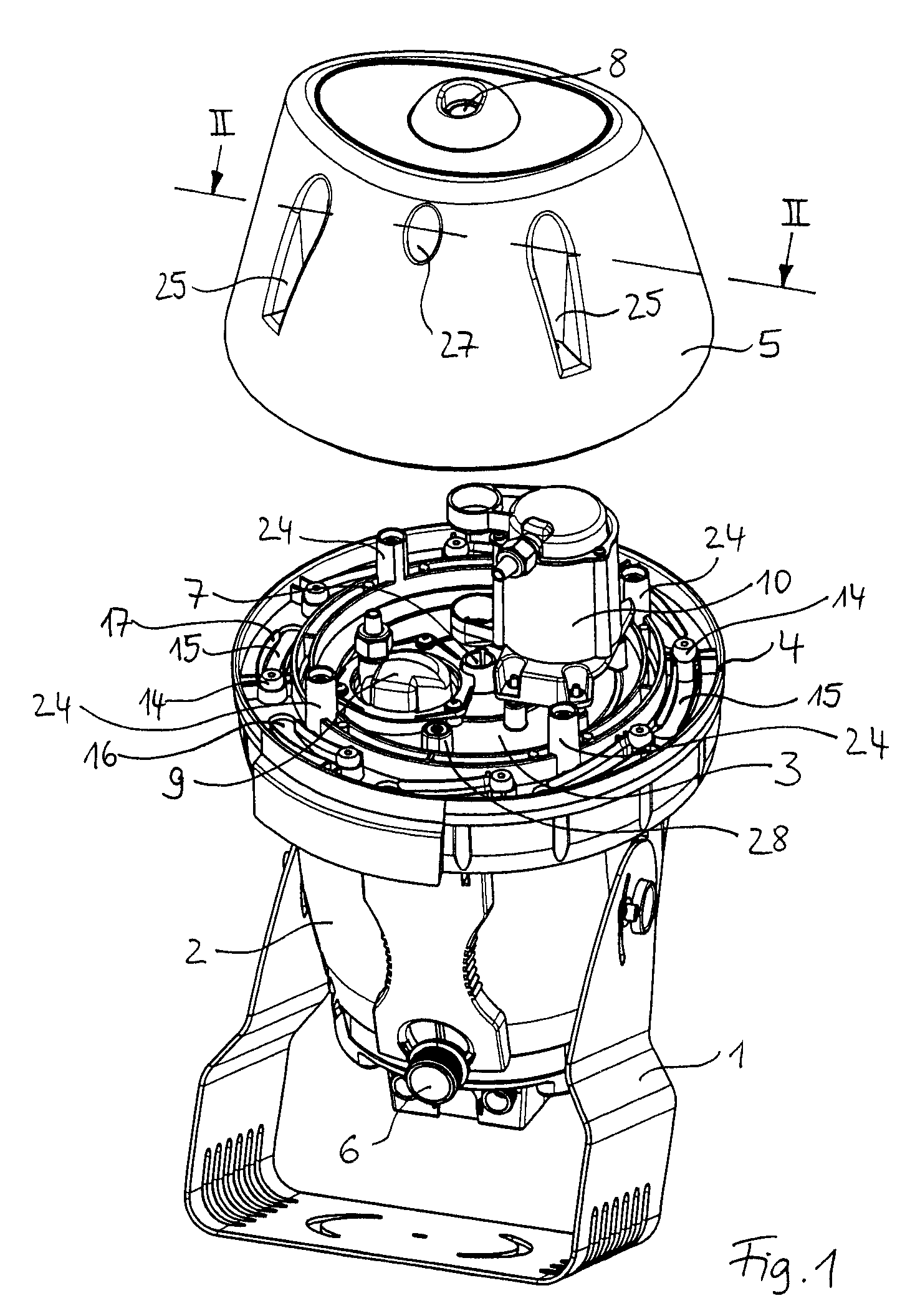
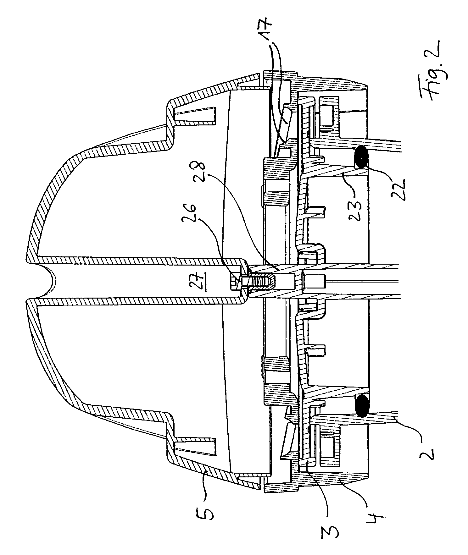
[0016]The invention will be explained in more detail with the aid of an embodiment in the form of a fountain jet generator that is illustrated most complete in FIG. 1. It is comprised of a pressurized water container connected to a support 1 and has a housing comprised of several housing parts 2, 3, 4, 5. The lower housing part 2 forms substantially the water container and is filled predominantly with filter foams, not illustrated, for calming the water. Through the inlet 6 water is conveyed under pressure into the container by means of a pump, not illustrated, and exits from the container through a nozzle 7 and a water outlet 8. The nozzle 7 is formed in a housing part 3 that closes off the area receiving the water in the upward direction which housing part will be explained in more detail later on. Above the housing part 3 further components are provided such as e.g. a turbulence generator 9 and an alignment actuator 10. The entire housing is closed off at the top by a lid 5. As c...


PUM


Abstract

A pressurized water container for water fountains, ponds, swimming pools, and aquariums has at least two housing parts and at least one seal arranged between the at least two housing parts, wherein the at least two housing parts are connectable to one another in a lockable way. The at least two housing parts have projections and matching recesses, wherein the projections engage the recesses and, by a displacement of the at least two housing parts relative to one another in opposite directions, they are lockable on one another and releasable from one another when reversing the displacement.

Description

BACKGROUND OF THE INVENTION[0001]The invention concerns a pressurized water container as it is used in connection with water fountain, pond, swimming pool or aquarium technology. Such pressurized water containers comprise at least two housing parts, between which at least one seal is arranged and which are connectable to one another in a lockable way. Water is forced through such containers under pressure and in this way, for example, filtered, supplied to a nozzle, or subjected to other similar mechanical actions. The container as well as the components arranged therein require a certain maintenance so that the container must be designed to be opened and closed again. Upon closing it is important to reinstate water seal-tightness that withstands the water pressures in operation. Conventional closure mechanisms are, for example, the connection of the housing parts by means of several clamps or toggle closures or by engaging a flange provided on both housing parts by means of a clamp...

Claims


Application Information

Patent Timeline
Patent Type & Authority Patents(United States)
IPC IPC(8): F16L17/00F16B23/00E03B9/20F16L55/00F16L39/00
CPCA01K63/04B05B17/08
Inventor BRUNE, DOMINIK
Owner OASE GMBH
Why Eureka
Try Eureka