
Lamp for side-marker, clearance or combination thereof

a technology of side marks and lamps, applied in the field of lamps, can solve the problems of inefficiency of such lights as vehicles, inability to optimize to its fullest extent, and more power efficiency, and achieve the effect of maintaining uniform heat distribution and dissipation, and low profil

Active Publication Date: 2012-08-28
INNOVATIVE LIGHTING LLC
View PDF20 Cites 1 Cited by
  • Summary
  • Abstract
  • Description
  • Claims
  • Application Information

AI Technical Summary

Benefits of technology

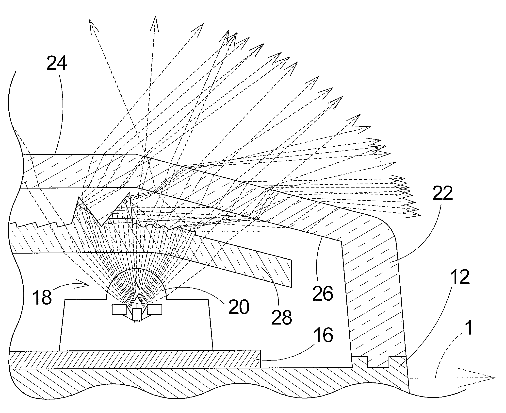
[0008]To meet these needs, the present invention generally provides an LED powered combination side-marker and clearance lamp that significantly redistributed light at an angle to the lamp's base, maintains a low profile, has a streamlined outer lens and maintains even heat distribution and dissipation.
[0009]One aspect of the present invention is that the redirection of light is accomplished in a two stage method wherein the light output of the LED is first passed through a first or interim lens that refracts a portion of the light at an angle and then passes through the outer cover of the lamp that may use a refractory inner topography to increase the angle of the light while maintaining a smooth and streamlined exterior.
[0010]Another beneficial aspect of the present invention is increased angular output of light while retaining the advantage of being low profile and decreasing drag on the vehicle and encountering less damage from collision and vibration.
[0011]Yet another aspect of the present invention would include avoiding problems with excess heat as the LEDs would enjoy a relatively open chamber for heat distribution and dissipation thus extending the life of the LED. Furthermore the interim lens may be constructed from a thermally conductive material that would aid in distributing heat across the entire lamp for easy dissipation though the cover and / or base.
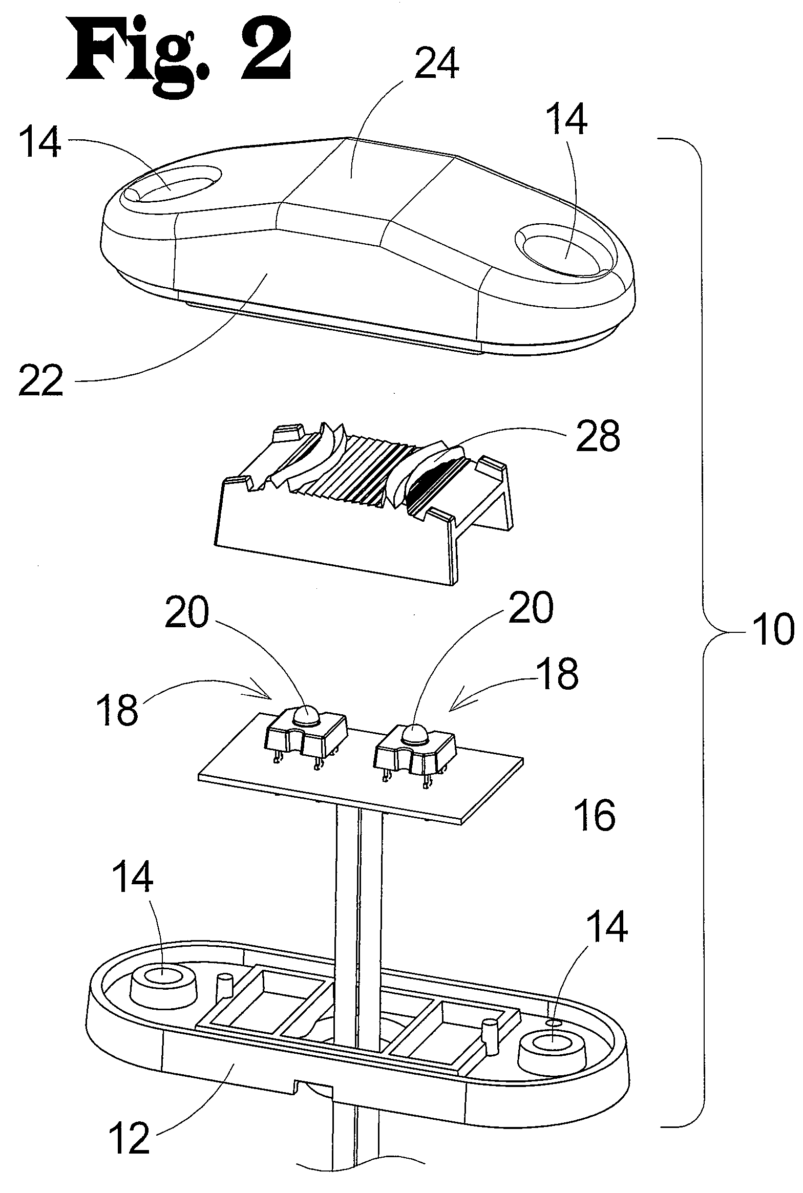
[0012]An additional aspect of the present invention is that the interim lens of the present invention would be designed as a drop-in element of the outer lens / cover which would be easily manufactured and integrated into an automated or manual manufacturing process.

Problems solved by technology

The ongoing transition from incandescent light sources to light emitting diode light sources has made such lamps smaller and more power efficient but the limitations set by this new LED technology has not yet been optimized to its fullest extent.
This fact points up the inefficiency of such lights as a vehicle is, even without illumination, most visible when viewed from a perpendicular angle.
The first method attempted to meet the need included having the light sources mounted high off the base of the lamp or angled at a slope in relation to the base, but the problems of having a high profile are obvious.
Susceptibility to damage, increased drag and vibration made these solutions unacceptable in the market
These have proven effective but introduce several problems such as a high profile prominence and non-streamlined outer surface of the exterior of the lamp that causes increased drag, resonant harmonic noise and vibrations as well as collection points for road dirt and debris that reduce the overall light output.
These too have proven effective but introduce certain problems.
The first of which is difficulty in manufacturing, in that fitting metal or plastic reflective chambers around each LED is a non-automated task requiring significant amounts of time and can reduce manufacturing yields and efficiency.
The second is over heating due to the lack of heat distribution which is inhibited by the isolation of the reflective surfaces.
Increased heat is known to reduced LED's lifespan and therefore the operational duration of any such lamp.

Method used


Image

  • Lamp for side-marker, clearance or combination thereof
  • Lamp for side-marker, clearance or combination thereof
  • Lamp for side-marker, clearance or combination thereof

Examples


Embodiment Construction

[0021]In the following detailed description, reference is made to the accompanying drawings which form a part hereof, and in which is shown by way of illustration specific embodiments in which the invention may be practiced. These embodiments are described in detail sufficient to enable those skilled in the art to practice the invention, and it is to be understood that other embodiments may be utilized and that structural, logical and mechanical changes may be made without departing from the spirit and scope of the present invention. The following detailed description is, therefore, not to be taken in a limiting sense, and the scope of the present invention is defined by the appended claims.

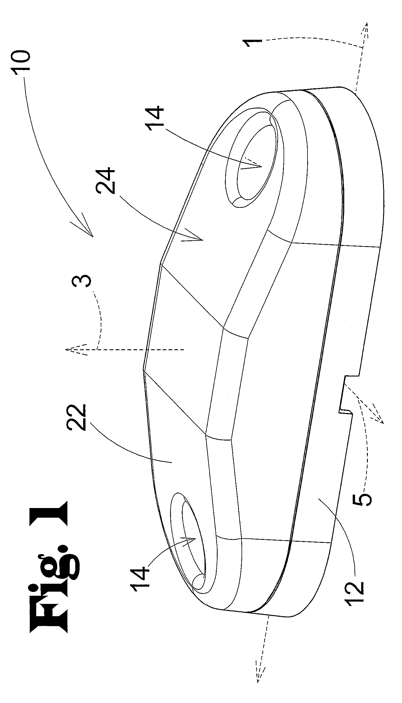
[0022]Illustrated in FIG. 1 is a lamp (10), representing a preferred embodiment of the present invention. The lamp (10) includes a base (12), a light source (22) and a cover exterior (24). The base (12) is adapted to be mounted to a vehicle and is intended to support the constituent elements of t...


PUM


Abstract

A low profile, streamlined, lamp for use as a side-marker and / or a clearance light on a vehicle which directs a substantial amount of its light output at an angle left and right of the perpendicular axis, and along the longitudinal axis through the agency of an optical element positioned between the light source and the outer cover.

Description

FIELD OF THE INVENTION[0001]The present invention relates to a lamp for indicating by illumination the boundary and or physical characteristics of a vehicle.BACKGROUND OF THE INVENTION[0002]Lamps used to illuminate moving vehicles have a long history within our technology. The ability to identify the size and type of vehicle is necessary to maintain safety on our roads and highways. The ongoing transition from incandescent light sources to light emitting diode light sources has made such lamps smaller and more power efficient but the limitations set by this new LED technology has not yet been optimized to its fullest extent.[0003]Within the industry of side-marker and clearance lamps there still exists many needs that have yet to be addressed by current technology, chiefly among these needs, is the need to control the light distribution of the LEDs in directions most beneficial to the use of such lamps. Most side-marker and clearance lights to date, direct the majority of their ligh...

Claims


Application Information

Patent Timeline
Patent Type & Authority Patents(United States)
IPC IPC(8): F21V1/00
CPCB60Q1/2696B60Q1/32F21V5/045F21Y2101/02F21Y2115/10
Inventor BAUER, JOSHUA G.TRESE, PATRICK
Owner INNOVATIVE LIGHTING LLC
Learn More