Pipeline laying vessel and method of laying a pipeline

a technology of pipeline laying and pipeline, which is applied in the direction of pipe laying and repair, pipe/joint/fitting, mechanical equipment, etc., can solve the problems of pipeline slippage, small risk of pipeline slippage, and high cost of forgings, so as to achieve faster laying, reduce costs, and ensure the effect of pipeline laying

Inactive Publication Date: 2012-08-28
HEEREMA MARINE CONTRACTORS NEDERLAND SE
View PDF17 Cites 11 Cited by
  • Summary
  • Abstract
  • Description
  • Claims
  • Application Information

AI Technical Summary

Benefits of technology

[0005]The use of the at least one tensioner has its own specific advantages. One of said advantages is that smooth pipe sections can be used for the laying of the pipeline. This means that it is not required that suspension means are provided on the pipe sections. Said suspension means are generally forgings, like collars, provided on the pipe sections. Said forgings are expensive, which means that the costs for the laying of pipeline are significantly reduced when using the at least one tensioners. Furthermore, with the at least one tensioner the pipeline can be laid faster.
[0006]The use of the fixating means and lowering means has its own specific advantages. One of said advantages is that said procedure is more secure, especially when a relative heavy pipeline is being laid. The at least one tensioner fixate and lower the pipeline by make use of the friction between the tensioners and the pipeline. With the fixation of the pipeline by the tensioners, there is always the (small) risk that the pipeline slips away. Because of the fixating means and lowering means use a clamp, said slipping away of the pipeline is prevented.
[0007]Further, to generate the required amount of friction when laying heavy pipes, one or more very large tensioners will be required, gripping the pipe over a large length. The at least one tensioner is preferably located below a work station (preferably suitable for welding) in a pipelay tower. To accommodate such large tensioner(s) in a pipelay tower would lead to a high and heavy construction. Fixating and lowering means are able to transfer the forces from the pipeline to the vessel over a much shorter height. The use of fixating and lowering means is therefore preferred for heavy pipelines.

Problems solved by technology

Said forgings are expensive, which means that the costs for the laying of pipeline are significantly reduced when using the at least one tensioners.
With the fixation of the pipeline by the tensioners, there is always the (small) risk that the pipeline slips away.

Method used


Image

  • Pipeline laying vessel and method of laying a pipeline
  • Pipeline laying vessel and method of laying a pipeline
  • Pipeline laying vessel and method of laying a pipeline

Examples


Embodiment Construction

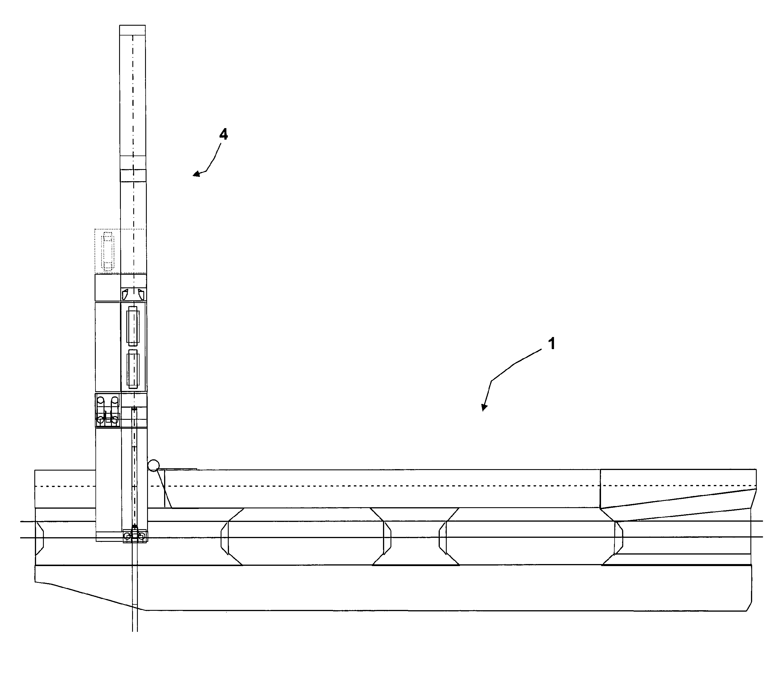
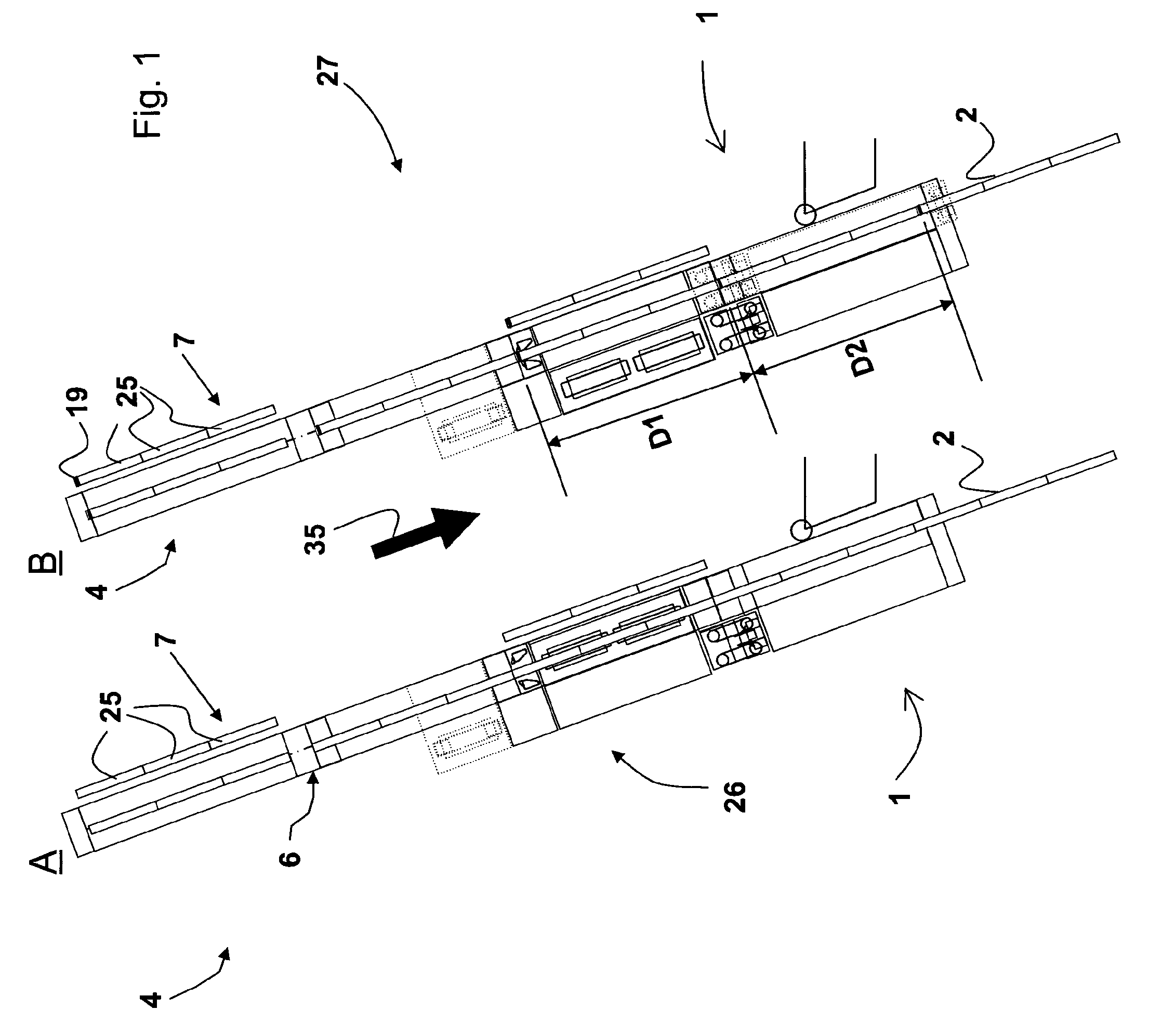
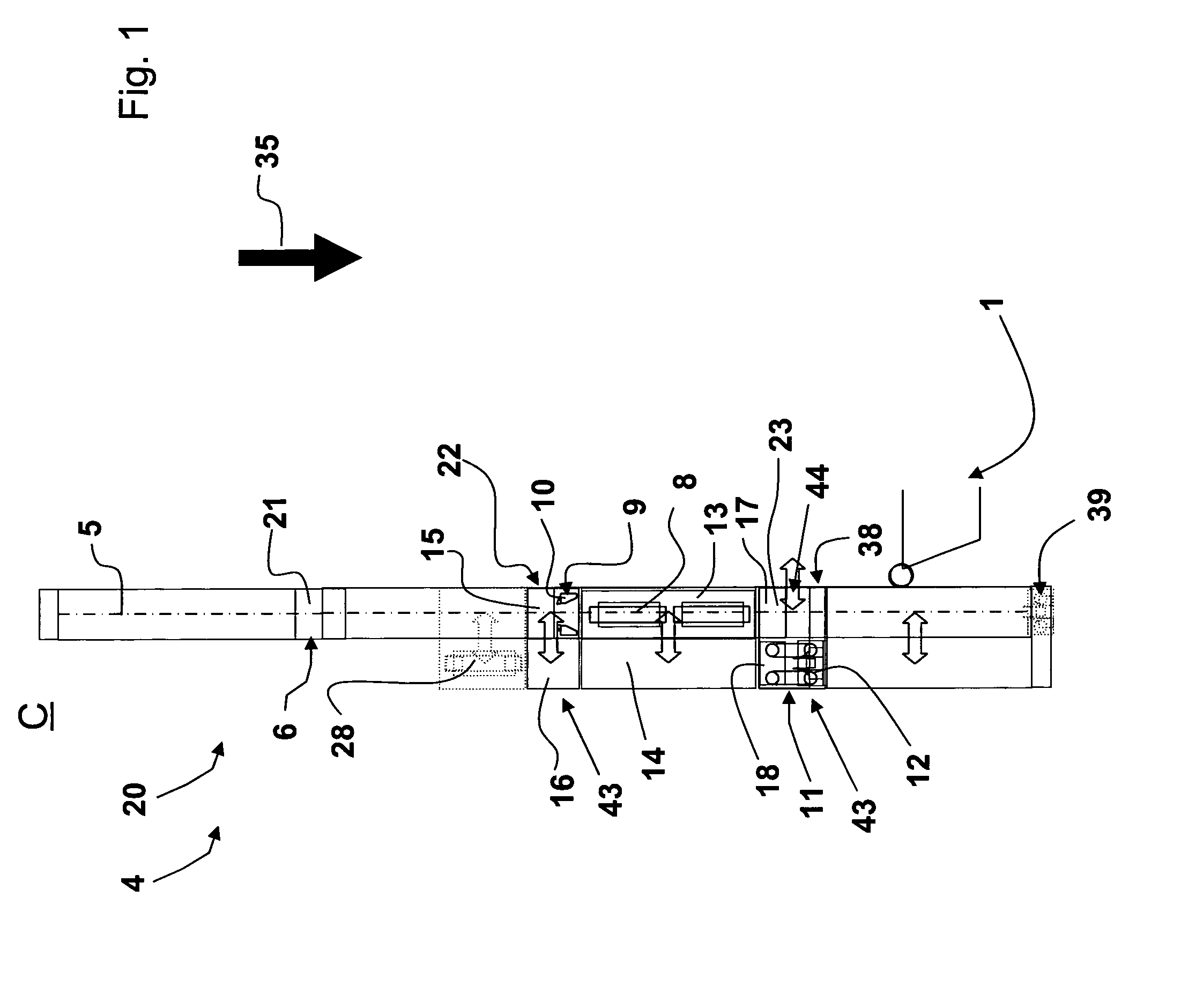
[0069]FIG. 1A-C shows a pipelaying vessel according the invention. Said vessel comprises a J-lay tower comprising a combined firing line. A J-Lay concept is developed with a combined firing line, the firing line combining the use of tensioners and the use of fixating means comprising a fixating clamp and lowering means comprising a lowering clamp. The tensioners may be used on smooth pipe up to top tensions of 600 T and the fixating and lowering means may be used (preferably in combination with collars provided on the pipeline) for heavy pipe with top tensions between 600 and 2000 T and for the installation of in-line structures, PLETs, flex-joints, etc.

[0070]The shown pipeline laying vessel 1 for laying a pipeline 2 at a seabed 3 comprises a tower 4, which tower 4 comprises a firing line 5 along which in use the pipeline 2 is laid and at least one work station 6 for connecting a pipe section 7 to the pipeline 2. The tower 4 comprises tensioners 8 for fixating and lowering the pipel...


PUM


Abstract

The invention relates to a pipeline laying vessel (1) for laying a pipeline (2) at a seabed (3) and comprising a tower (4) comprising a firing line (5) along which in use the pipeline is laid and at least one work station (6) for connecting a pipe section (7) to a suspended pipeline and a method of laying pipeline at a sea bed with such a pipe laying vessel.

Description

CROSS-REFERENCE TO RELATED APPLICATIONS[0001]This application is the National Stage of International Application No. PCT / NL2008 / 000097, filed Apr. 2, 2008, which claims the benefit of U.S. Provisional Application No. 60 / 907,416, filed Apr. 2, 2007, the contents of which is incorporated by reference herein.FIELD OF THE INVENTION[0002]This invention relates to a pipeline laying vessel for laying a pipeline at a seabed and comprising a tower comprising a firing line along which in use the pipeline is laid and at least one work station for connecting a pipe section to a suspended pipeline and a method of laying a pipeline at a sea bed with such a pipe laying vessel.SUMMARY OF THE INVENTION[0003]The tower may comprise at least one tensioner for fixating and lowering the pipeline. The tower may instead or in addition comprise fixating means for fixating the pipeline, which fixating means comprise a fixating clamp, and lowering means for fixating and lowering the pipeline, which lowering m...

Claims


Application Information

Patent Timeline
Patent Type & Authority Patents(United States)
IPC IPC(8): F16L1/19F16L1/20F16L1/23
CPCF16L1/19F16L1/23F16L1/207
Inventor NAROLD, ROBERT REINDERVAN ZANDWIJK, CORNELISSPANJERS, COEN MAARTEN
Owner HEEREMA MARINE CONTRACTORS NEDERLAND SE
Why Eureka
Try Eureka