System for remote guidance by expert for imaging device

a technology for imaging devices and experts, applied in the field of imaging display devices, can solve the problems of impede or hinder the effective completion of a particular task, human eyes cannot see into the interior sections of a non-transparent, solid object, and lack of real-time visual feedback in the vicinity of critical structures

Active Publication Date: 2012-08-28
UNIVERSITY OF PITTSBURGH
View PDF53 Cites 11 Cited by
  • Summary
  • Abstract
  • Description
  • Claims
  • Application Information

AI Technical Summary

Problems solved by technology

In other words, humans cannot see into the interior sections of a non-transparent, solid object.
Quite often, and in many different technology areas, this sight limitation may impede or hinder the effective completion of a particular task.
One potential problem with such procedures is the lack of real-time visual feedback in the vicinity of critical structures such as the hepatic arteries.
This system typically requires a clinician to look away from his hands at a video monitor, resulting in a loss of direct hand-eye coordination.
As a further disadvantage, the needle-guide system constrains the biopsy needle to lie in the image plane, whereas the clinician may prefer the needle to intersect the image plane during some invasive procedures.
The prior art system just described may not be capable of accomplishing this task.
These prior art systems may not be appropriate for use with a practical real-time imaging device.
Controlling the multiple degrees of freedom can be difficult, and the systems may have too many complex parts to be useful.
However, it may be physically impossible for the medical professional to be present in sufficient time to save the life of the solider.

Method used


Image

  • System for remote guidance by expert for imaging device
  • System for remote guidance by expert for imaging device
  • System for remote guidance by expert for imaging device

Examples


Embodiment Construction

[0039]It is to be understood that the figures and descriptions of the present invention have been simplified to illustrate elements that are relevant for a clear understanding of the invention, while eliminating, for purposes of clarity, other elements that may be well known. The detailed description will be provided hereinbelow with reference to the attached drawings.

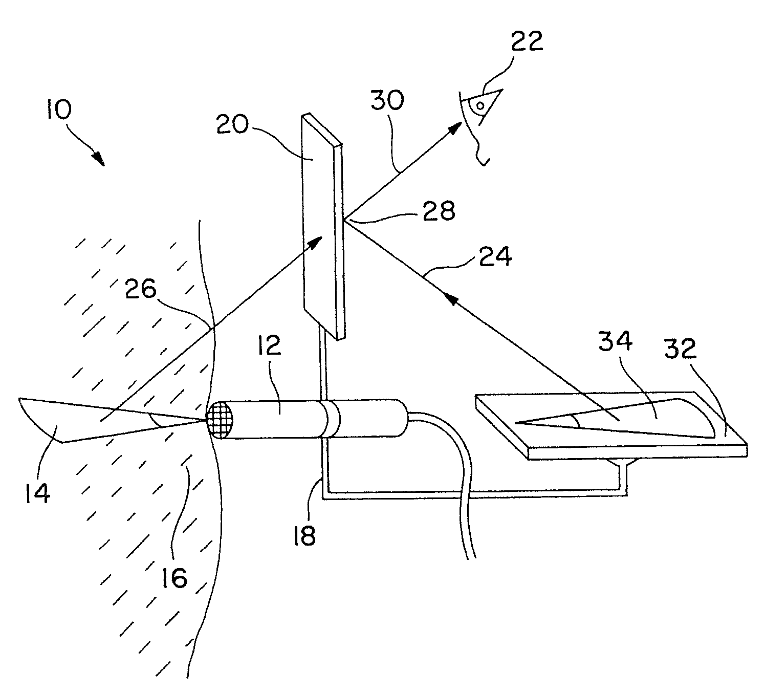
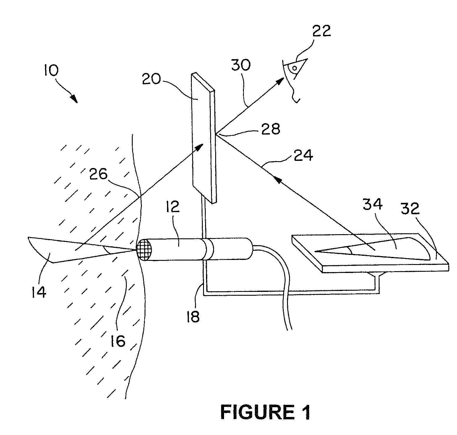
[0040]The invention contemplates, in at least one presently preferred embodiment, a method and device for merging or superimposing the reflection of a two dimensional tomographic image of the interior of a target object with the normal human vision view of the outside of that same target object. This methodology may be used in any application where viewing the interior of an object is desired, and the methodology is not limited to any particular industry or application. In some embodiments, the present invention is applied to medical procedures where an in situ image of tissue provides valuable information for the medi...


PUM


Abstract

Systems and methods for combining tomographic images with human vision. The systems preferably include a first assembly located proximal to an object to be imaged and a second assembly remote from the target. The first assembly is preferably able to collect a tomographic image from a target object and superimpose that tomographic image onto a direct view of the target object. The first assembly also includes components that allow the transmission of the tomographic image to the remote assembly. At the remote location, a highly trained expert may interact with the captured image by placing electronic markers on the image via an electronic interface. The captured image plus electronic marker are then preferably transmitted back to the local site via a second transmitter-receiver. The local user may use the electronic marker to guide his actions during the appropriate task. The systems have particular utility in the medical field where a trained clinician at a remote location may provide guidance to an untrained individual in performing a medical procedure on a patient.

Description

RELATED APPLICATION[0001]This application claims the benefit of U.S. provisional application No. 60 / 893,245 filed Mar. 6, 2007 and is a continuation-in-part of U.S. application Ser. No. 10 / 126,453 filed Apr. 19, 2002 (now U.S. Pat. No. 7,559,895, issued Jul. 14, 2009), which is a continuation-in-part of U.S. application Ser. No. 09 / 686,677 filed Oct. 11, 2000 (now U.S. Pat. No. 6,599,247, issued Jul. 29, 2003).BACKGROUND OF THE INVENTION[0002]1. Field of the Invention[0003]The present invention generally relates to image display devices and methods of using the same. More particularly, the present invention relates to methods and devices for combining a reflection of a tomographic image with human vision during subcutaneous medical procedures in which a user may remotely interact with and provide guidance for the medical procedure being performed.[0004]2. Description of the Background[0005]Because human vision depends at least partially on the detection of reflected visible light, h...

Claims


Application Information

Patent Timeline
Patent Type & Authority Patents(United States)
IPC IPC(8): H04N13/02
CPCA61B8/0833A61B8/587A61B8/462A61B8/467A61B8/5238A61B19/52A61B8/0841A61B19/201A61B19/5212A61B2019/223A61B2019/262A61B2019/507A61B2019/5231A61B2019/5236A61B2019/5276A61B2019/5291A61B2090/502A61B90/36A61B2090/373A61B90/361A61B90/11A61B34/35A61B2034/107A61B2090/374A61B2090/378A61B2090/365
Inventor STETTEN, GEORGE DEWITT
Owner UNIVERSITY OF PITTSBURGH
Why Eureka
Try Eureka