
Solid-state ultra-wideband microwave power amplifier employing modular non-uniform distributed amplifier elements

a technology of distributed amplifier elements and solid-state microwaves, which is applied in the direction of amplifiers with semiconductor devices/discharge tubes, amplifier modifications to extend bandwidth, amplifiers with only semiconductor devices, etc., can solve the problems of source of output attenuation, non-uniform distribution of amplifier strings, and only real input and output impedances, etc., to achieve uniform power output capability, increase power level, power and efficiency

Active Publication Date: 2011-04-12
GULA CONSULTING LLC
View PDF10 Cites 10 Cited by
  • Summary
  • Abstract
  • Description
  • Claims
  • Application Information

AI Technical Summary

Benefits of technology

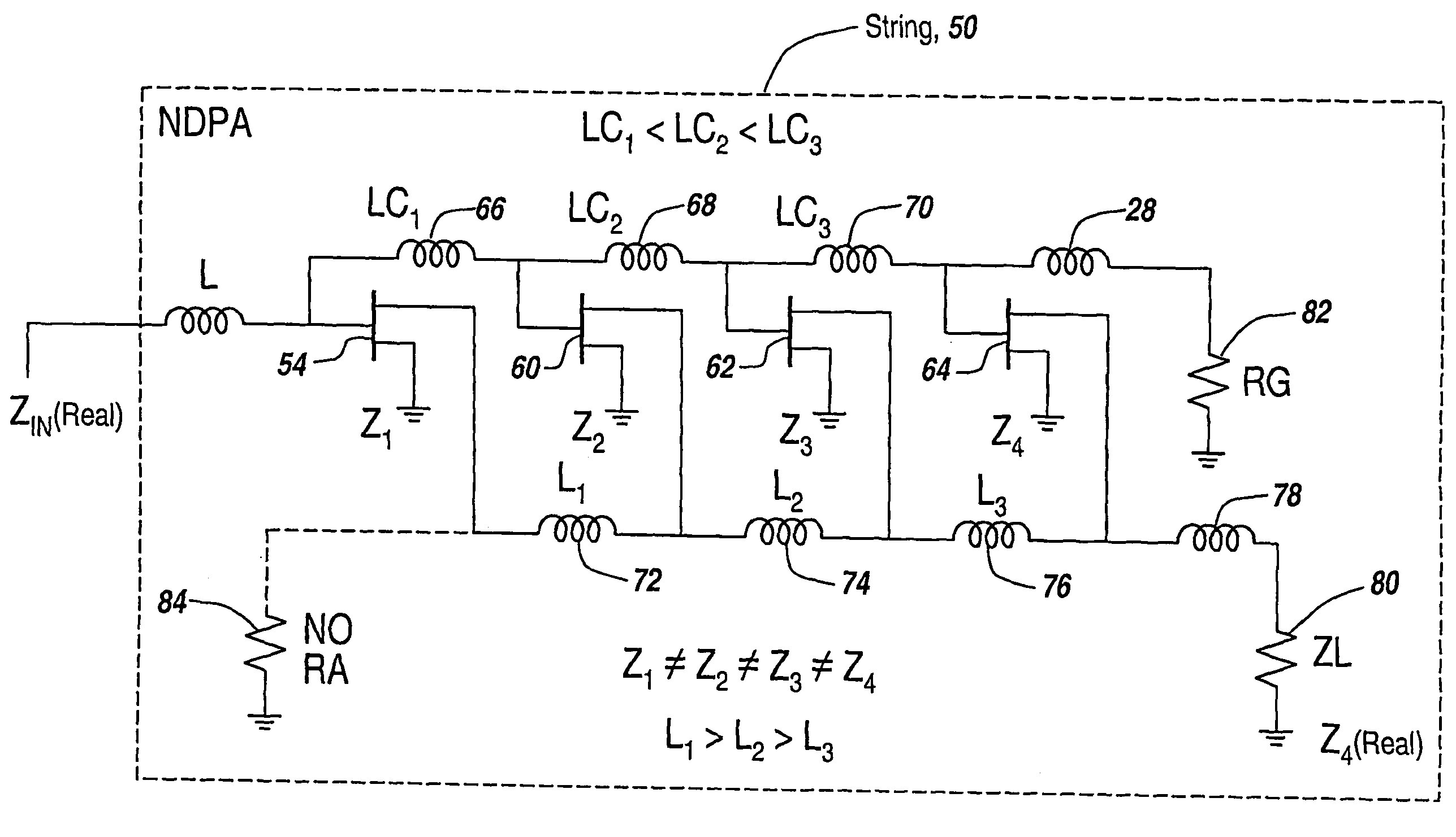
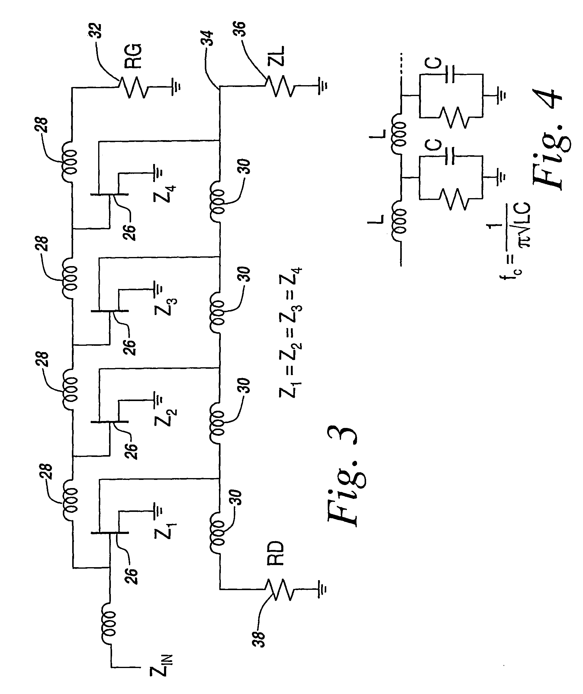
The patent describes a new type of power amplifier that uses a non-uniform distribution of amplifier building blocks to achieve wideband amplification. These blocks have real input and output impedances, which makes it easy to connect them in parallel for added power or cascaded for increased gain. The non-uniform distribution of impedance values also absorbs parasitic capacitance, simplifies manufacturing, and enables high power output with stable output levels. The amplifier can be designed to have input and output impedances that are real, and no drain loads are required. Combining multiple strings of the amplifier allows for high power output with flat frequency response. Overall, the non-uniform distributed power amplifier has improved performance and reliability compared to traditional traveling wave tubes and has applications in high-speed circuits and RF power amplification.

Problems solved by technology

It has been found that non-uniformly distributed amplifier strings have only real input and output impedances.
First, the amplifier does not use a drain line termination, which removes this as a source of output attenuation.

Method used


Image

  • Solid-state ultra-wideband microwave power amplifier employing modular non-uniform distributed amplifier elements
  • Solid-state ultra-wideband microwave power amplifier employing modular non-uniform distributed amplifier elements
  • Solid-state ultra-wideband microwave power amplifier employing modular non-uniform distributed amplifier elements

Examples


Embodiment Construction

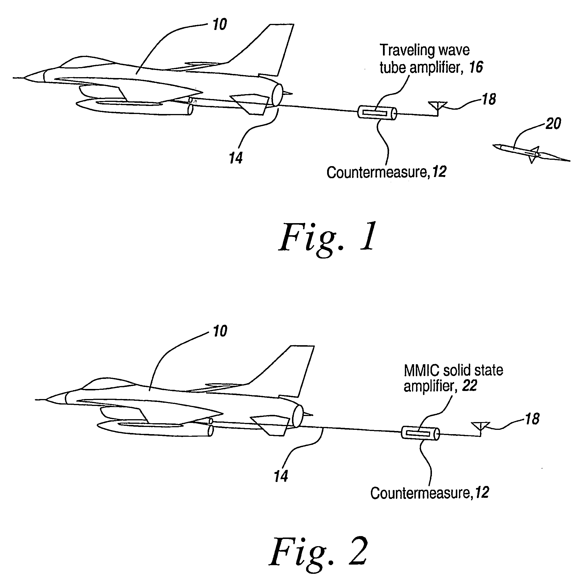
[0070]Referring now to FIG. 1, for electronic warfare applications an aircraft 10 tows a countermeasure vehicle 12 using a towline 14. Vehicle 12 carries a traveling wave tube amplifier 16 coupled to an antenna 18, with the towline in general being a fiber optic cable that, in addition to functioning as a tow cable, transmits control signals and high DC voltage to the traveling wave amplifier.

[0071]The purpose of the countermeasure vehicle is to transmit jamming or countermeasure radiation from antenna 18 that is designed to confuse or countermeasure missiles that utilize active radars in their seekers.

[0072]Traveling wave tube amplifiers provide broadbanded amplification and are programmed to alter incoming signals from the seeker of an approaching missile 20 and project back the altered signals and amplified versions of the incoming signals towards the missile.

[0073]As mentioned hereinbefore, the subject non-uniform distributed amplifier is a solid-state amplifier that replaces th...


PUM


Abstract

A number of identical non-uniformly distributed ultra-wideband power amplifier string building blocks are coupled together to form an ultra-wide bandwidth high-power amplifier. The non-uniform distribution results in an amplifier utilizing modular string building blocks that have input and output impedances with only real values. This permits the strings to be replicated and connected together with simple impedance matching. The internal impedance matching associated with the non-linear distribution also absorbs parasitic capacitance to permit the ultra-broadband operation. In one embodiment identical transistors are used for each cell so that the strings may be identically replicated. This permits modular re-use without reconfiguration. In one embodiment a non-uniform distributed power amplifier built using the subject building blocks provides an ultra-wideband multi-octave device suitable for electronic warfare and communications applications, especially to replace traveling wave tubes.

Description

RELATED APPLICATIONS[0001]This Application claims rights under 35 USC §119(e) from U.S. Application Ser. No. 60 / 630,343 filed Nov. 23, 2004, the contents of which are incorporated herein by reference.FIELD OF THE INVENTION[0002]This invention relates to solid-state microwave power amplifiers and more particularly to achieving multi-octave frequency bandwidths using non-uniformly distributed amplification modular building blocks.BACKGROUND OF THE INVENTION[0003]Ultra-wide bandwidth power amplifiers that can, for instance, produce 100-watt microwave outputs in the past have utilized traveling wave tubes. One application for such high-power microwave traveling wave tube amplifiers is in electronic warfare to countermeasure radar-based seekers by emitting jamming signals. In many of these applications a traveling wave tube amplifier is towed in a vehicle behind an aircraft and is provided with a high-voltage source to run the traveling wave tube. Control and modulating signals are also ...

Claims


Application Information

Patent Timeline
Patent Type & Authority Patents(United States)
IPC IPC(8): H03F3/60
CPCH03F1/42H03F3/195H03F3/211H03F3/604H03F3/607H03F2203/21178H03F2200/453H03F2200/543H03F2203/21106H03F2203/21142H03F2200/39
Inventor LENDER, JR., ROBERT J.ACTIS, ROBERT
Owner GULA CONSULTING LLC
Learn More