Al technical title is built by PatSnap Al team. It summarizes the technical point description of the patent document.
a control circuit and control circuit technology, applied in the field ofalternator systems, can solve the problems of heavy load regulation, strong influence of inductance on machine performance, and increase in output current and machine operating speed with increasing output current and machine operating speed, and achieve low cost, high power level, and power output improvement
Inactive Publication Date: 2005-06-28
MASSACHUSETTS INST OF TECH
View PDF33 Cites 58 Cited by
Summary
Abstract
Description
Claims
Application Information
AI Technical Summary
This helps you quickly interpret patents by identifying the three key elements:
Problems solved by technology
Method used
Benefits of technology
[0026]With the present invention, relatively high power levels can be achieved within the existing manufacturing framework and with existing machine sizes at relatively low cost. Furthermore, the so-called load dump problem associated with Lundell and other wound field types of alternators is overcome by the addition of some control circuitry (e.g. a fault protection controller coupled to sense voltage levels at the output or at other locations of the alternator system), a relatively small change in the rectifier stage (e.g. coupling of the rectifier stage to the fault protection controller) and minor adjustments in the machine design so that the peak of the machine's output power versus output voltage curve for constant speed with diode rectification matches the desired output voltage at a desired cruising speed, and the system can additionally produce power output improvements at speeds near idle.
Problems solved by technology
One problem with wound-field Lundell-type alternators, however, is that the relatively high machine inductance strongly affects the machine performance.
In particular, due to the high inductance of the Lundell machine, it exhibits heavy load regulation when used with a diode rectifier.
That is, there are significant voltage drops across the machine inductances when current is drawn from the machine, and these drops increase with increasing output current and machine operating speed.
One problem with this approach, however, is that it can be relatively complex from a control point of view.
This approach, which typically utilizes a full-bridge converter circuit, often yields high performance at the expense of having many fully-controlled PWM switches and complex control circuits and techniques.
While regulating output voltage or current with a boost circuit of this type may be useful in permanent magnet alternators having relatively low inductance characteristics, this method is not useful with alternators having a relatively large inductance characteristic and a wide operating speed range such as in wound-field Lundell-type alternators for automotive applications.
However, if the internal machine voltages become significantly larger than the desired dc output voltage, then the output voltage cannot be regulated by the boost rectifier independent of load without inducing unacceptably high currents in the machine.
The typical automotive Lundell alternator presents this problem.
However, design of these alternators is becoming increasingly more difficult due to continually rising power levels required in vehicles and in particular required in automobiles.
Additional power is not achieved at low speed (e.g. at idle) using this method, since there is insufficient voltage to forward bias the booster diodes in leg 18.
Method used
Image
Click on the blue label to locate the original text in one second.
Reading with bidirectional positioning of images and text.
Examples
Embodiment Construction
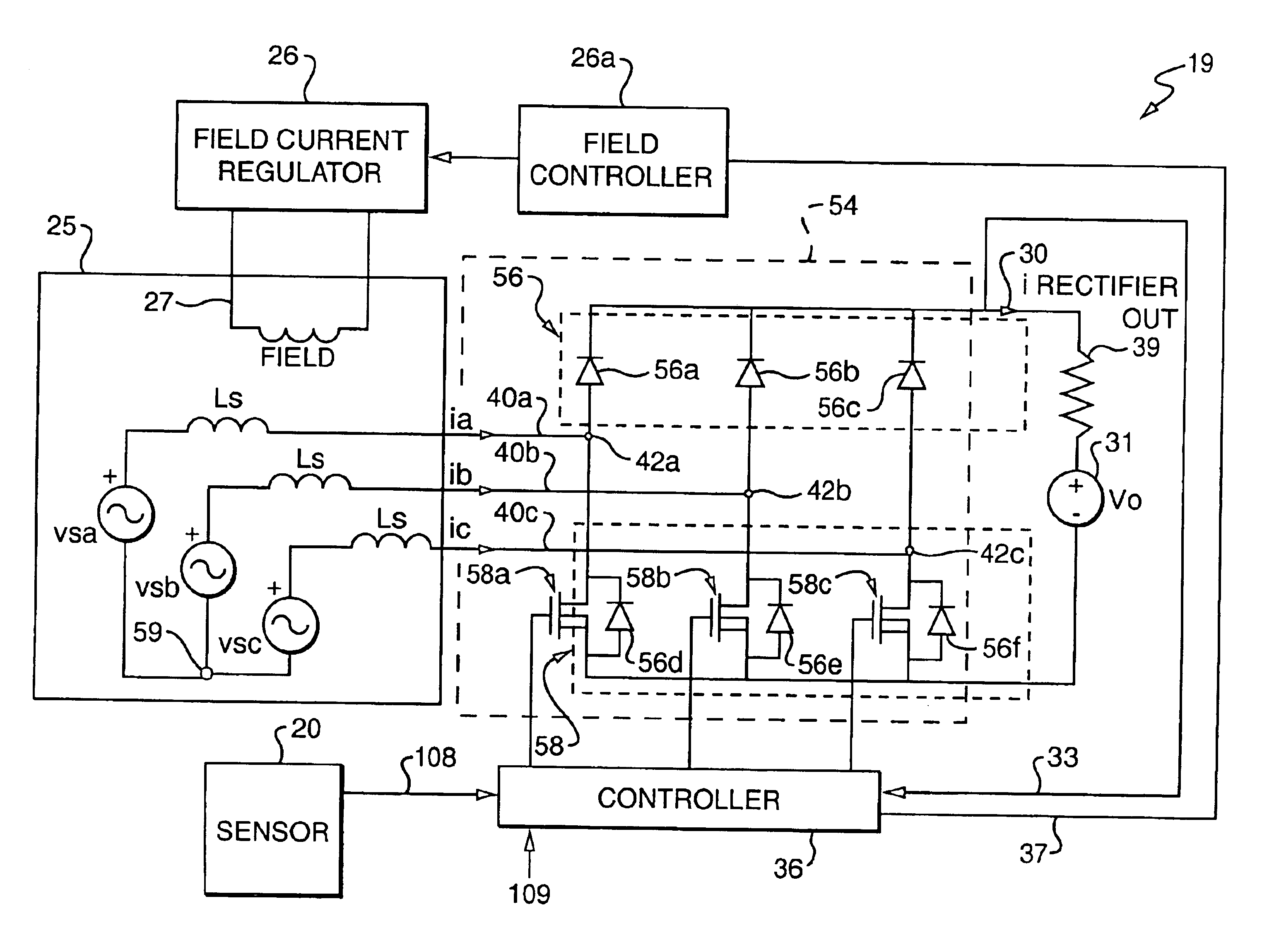
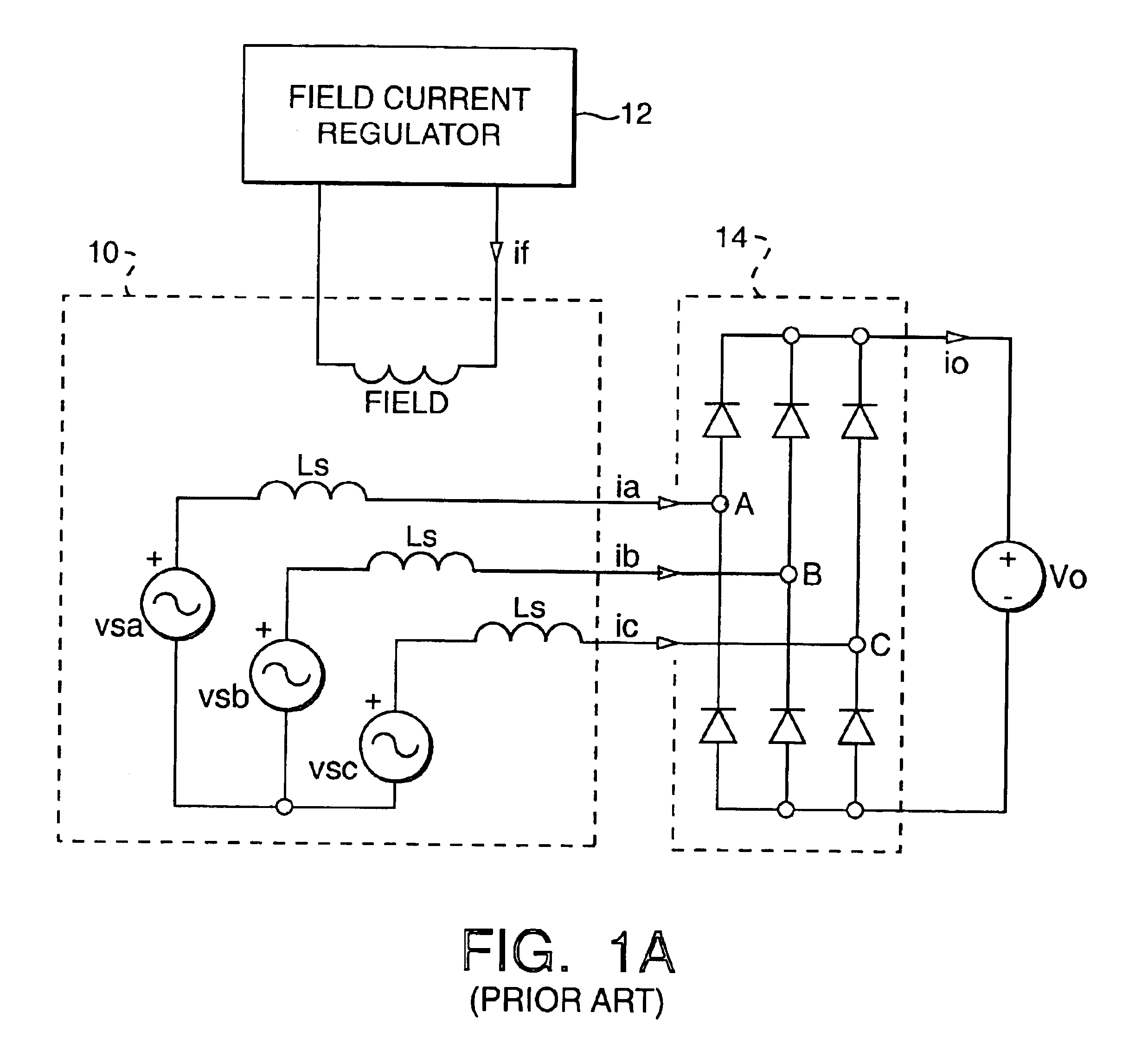
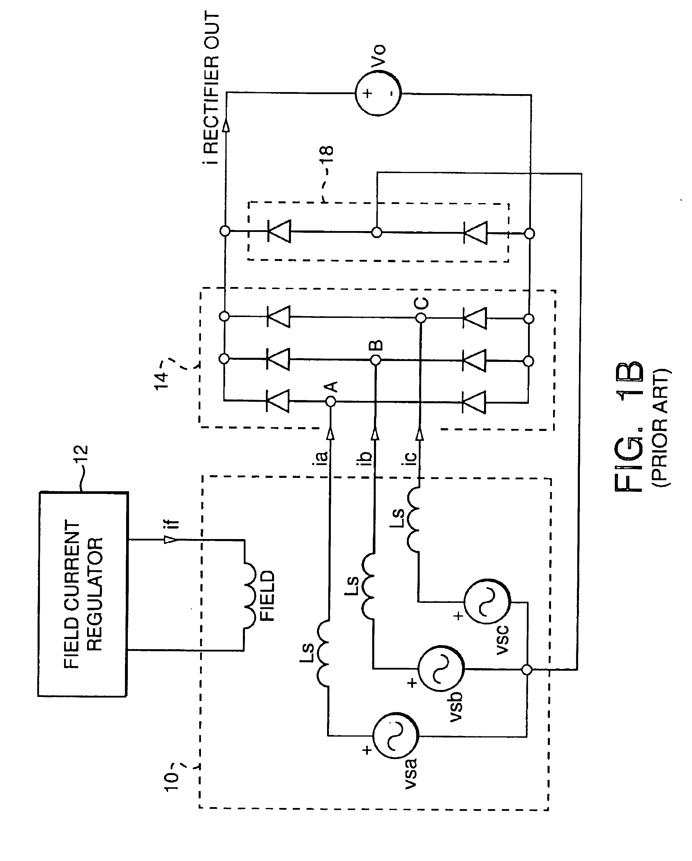
[0049]As noted above, those of ordinary skill in the art sometimes refer to the ac machine itself as an alternator while at other times those of ordinary skill in the art refer to the combination of the ac machine coupled to a rectifier circuit also as an alternator. To promote clarity in the text, the term “alternator system” will be used herein to describe a system which includes an ac generator portion and a rectifier portion. The ac generator portion may also be referred to as an “ac machine,” an “ac generator,” a “generator” or an “alternator” while the rectifier portion of an alternator system will be referred to herein as a “rectifier” or a “rectifier circuit.” The term “ac voltage source” is intended to cover any type of source which can be used with the present invention including but not limited to an alternator. The term “control circuit” or “controller” is intended to cover any type of discrete logic, microprocessor, and any combination of microprocessors and discrete lo...
PUM
Abstract
An alternator system having an alternating current (ac) voltage source includes a switched-mode rectifier (SMR) coupled to the ac voltage source and having an output port coupled to an output of the alternator system, and a controller coupled to said switched-mode rectifier so as to provide a controlled pulse sequence synchronized with an angular rotor position of the (ac) voltage source to activate and deactivate the switched-mode rectifier. The controller further includes a PWM generator having a first input to receive a total duty ratio signal synchronized with an angular rotor position of the (ac) voltage source. The switched mode rectifiers are controlled to increase power output levels at lower speeds near idle. The controller combines improved idle speed power output levels with load matching improvements from PWM control for more efficient operation when compared to circuits using conventional control or PWM load matching control alone.
Description
CROSS-REFERENCE TO RELATED APPLICATIONS[0001]This application claims the benefit of U.S. Provisional Application No. 60 / 242,327, filed on Oct. 20, 2000, which application is hereby incorporated herein by reference in its entirety. This application is a continuation-in-part of application Ser. No. 09 / 557,844, filed on Apr. 26, 2000, now U.S. Pat. No. 6,346,797, which claims the benefit of Provisional Application No. 60 / 177,752 filed on Jan. 24, 2000 and U.S. Provisional Application No. 60 / 184,006 filed on Feb. 22, 2000, which applications are hereby incorporated by reference in their entireties. This application is a continuation-in-part of application Ser. No. 09 / 558,193, filed on Apr. 26, 2000, now U.S. Pat. No. 6,456,514, which claims the benefit of Provisional Application No. 60 / 177,752 filed on Jan. 24, 2000 and U.S. Provisional Application No. 60 / 184,006 filed on Feb. 22, 2000, which applications are hereby incorporated by reference in their entireties.FIELD OF THE INVENTION[00...
Claims
Application Information
Patent Timeline
Application Date:The date an application was filed.
Publication Date:The date a patent or application was officially published.
First Publication Date:The earliest publication date of a patent with the same application number.
Issue Date:Publication date of the patent grant document.
PCT Entry Date:The Entry date of PCT National Phase.
Estimated Expiry Date:The statutory expiry date of a patent right according to the Patent Law, and it is the longest term of protection that the patent right can achieve without the termination of the patent right due to other reasons(Term extension factor has been taken into account ).
Invalid Date:Actual expiry date is based on effective date or publication date of legal transaction data of invalid patent.