
Thin walled thermoelectric devices and methods for production thereof

Inactive Publication Date: 2010-06-24
NEMIR DAVID +2
View PDF5 Cites 58 Cited by
  • Summary
  • Abstract
  • Description
  • Claims
  • Application Information

AI Technical Summary

Benefits of technology

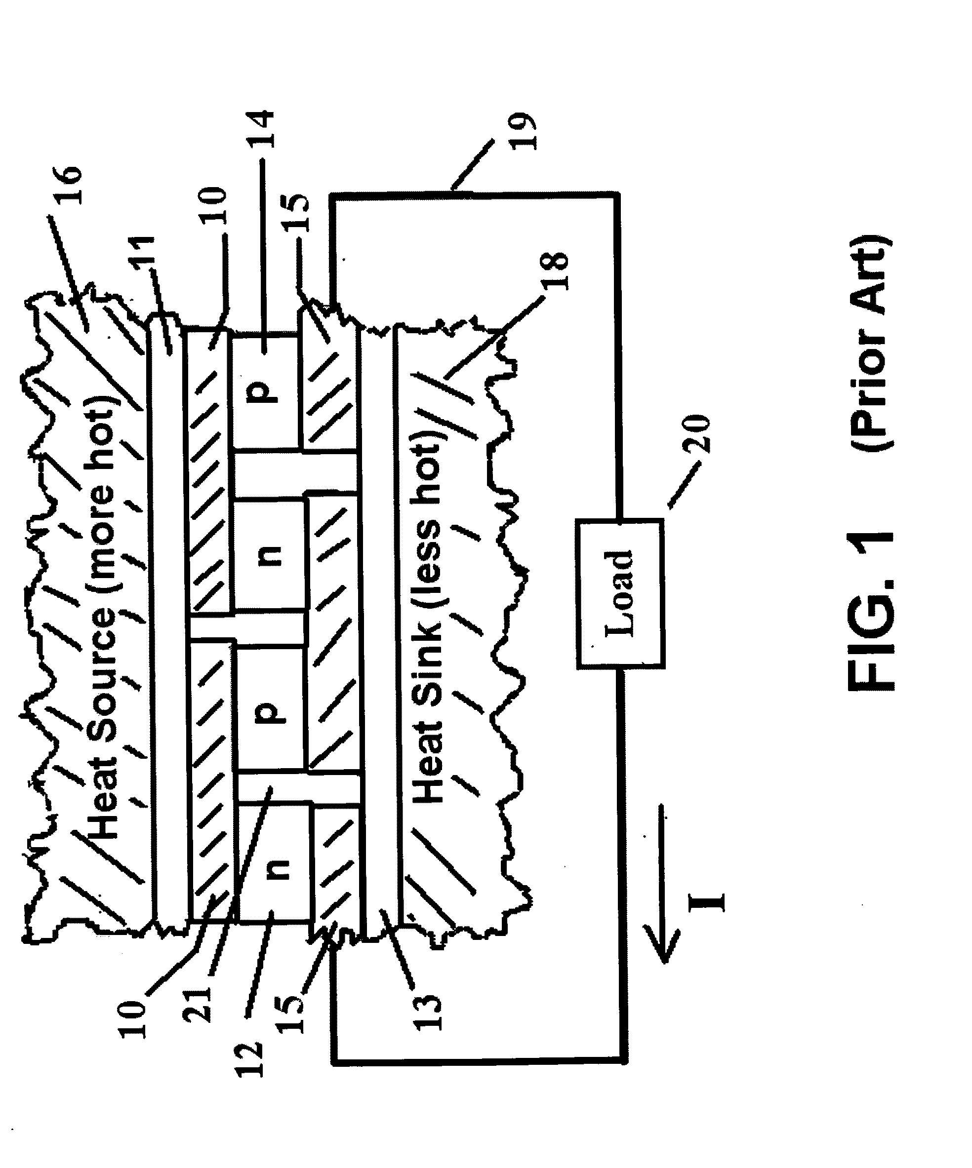
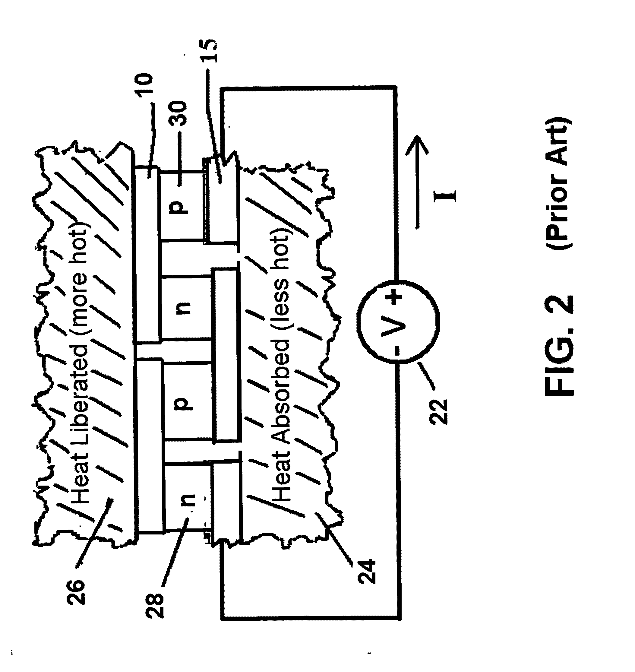
[0028]The present invention is for an apparatus and method of production of a thermoelectric device. The ability to add a thermoelectric generation capability by applying it in a coating to the surface of a conventional heat exchanger opens the doors to a myriad of possible applications in power plants, refineries and other applications. By selectively applying layers of dielectric, electrical conductor and N and P type thermoelectric material onto a heat exchanger wall, a thermoelectric generation capability can be added to a heat exchanger, allowing it to serve a dual purpose, producing bonus electricity in addition to its heat exchange design. When applied to the outside of a tube, the result is a thermoelectric generator in a versatile deployment vehicle for electric generation from hot and cold fluid streams and for geothermal deployments. A single such tube may be used for generating power, or multiple tubes may be used together in concert to increase generation power levels. This allows for flexibility in manufacture and deployment.
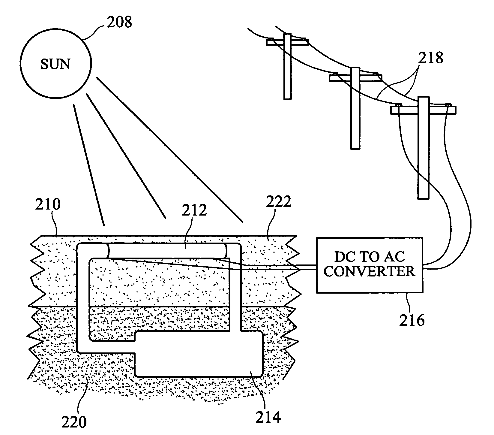
[0031]A tubular configured thermoelectric generator lends itself to harvesting thermal energy that is collected from the sun. One possible use is in a solar pond. A solar pond is a body of water that contains layers of salt solutions. The top layer has low salt content, the bottom layer has high salt content and the intermediate layer has an intermediate salt content and establishes a density gradient that prevents heat exchange by natural convection. Incident solar radiation heats up the bottom layer. The top layer serves to insulate this layer.
[0032]The difference in temperature may be on the order of 60 or more degrees Celsius. If a thermoelectric generator is configured around a tube, that tube can be used to transport salty water from lower levels through the upper levels, effectively acting as a heat exchanger. Since the system is a closed one, and it is only necessary to transport the fluid a vertical distance of, perhaps, a few feet, the pumping requirements are minimal. In this way, electric generation can be accomplished from a solar pond and solar energy that is collected over a relatively large area may be “harvested” from a single tube generator.

Problems solved by technology

A problem with this design is that since even the best thermoelectric materials have a Seebeck coefficient of only about 200 μV / ° C., it requires the series electrical connection of many tubes to obtain an appreciable voltage level.
Furthermore, the use of nested tubes adds thermal resistance between steam and chilling water, compromising the heat exchange function U.S. Pat. No. 6,367,261 B1 (Marshall et al) describes a thermoelectric power generator using a steam source and one or more thermoelectric modules embedded between nested condenser tubes.
In order to generate usable voltages through thermoelectric means, it is necessary to connect many couples in electrical series, a process which can be laborious and can lead to problems at the interfaces and interconnections.
This is a problem shared by status quo approaches to the design of thermoelectric generators for large scale power production.
These techniques are expensive manufacturing approaches when considered on a square meter of thermoelectric generator surface.
Furthermore, these techniques are not well suited for the volume production of devices having more than 1 μm in thickness.
Some techniques (eg: high velocity oxy-fuel) can result in the presence of oxygen and hydrocarbons in the powder which may alter the properties of the deposited materials.

Method used


Image

  • Thin walled thermoelectric devices and methods for production thereof
  • Thin walled thermoelectric devices and methods for production thereof
  • Thin walled thermoelectric devices and methods for production thereof

Examples


Embodiment Construction

[0237]In the following paragraphs, the present invention will be described in detail through examples and detailed drawings. Definitions of some of the terms used in describing the preferred embodiments are as follows:

Carnot limit—by the second law of thermodynamics, the theoretical limit on the ability of a device to convert thermal energy into work. The Carnot efficiency limit is given by η=(TH−TC) / TH where TH and TC are, respectively, the temperatures of the hot (source) and cold (sink) reservoirs.

Cold and hot side temperature—terms like hot reservoir, hotter side, cold side and colder reservoir are relative terms. In some implementations, the “hot” side of a thermoelectric device might be at ambient temperature while the “cold”side is at a cooler temperature than ambient. In other implementations, the “cold” side might be at ambient temperature while the “hot” is at a warmer than ambient temperature. In still other implementations, the terms “hot” and “cold” might have no relati...


PUM


Abstract

A thermoelectric generator is built into the wall of a heat exchanger by applying coatings of dielectric, electrical conductor and N-type and P-type thermoelectric materials. A tubular heat exchanger lends itself to the application of coatings in annular rings, providing ease of manufacture and a structure that is robust to damage.

Description

REFERENCE TO PRIOR PROVISIONAL APPLICATION[0001]This application claims the benefit of the filing date of prior filed U.S. Provisional Patent Application No. 61 / 138,574 filed Dec. 18, 2008, which is incorporated herein by reference as if written herein in its entirety.BACKGROUND OF THE INVENTION[0002]1. Field of the Invention[0003]This invention relates to thermoelectric devices and methods for building such devices into the walls of heat exchangers.[0004]2. Background of the Invention[0005]Thermoelectric phenomena arise out of the intercoupled electrical and thermal currents in a material. A thermoelectric generator may be viewed as a mechanism for energy conversion, transforming energy in one form (heat) into another form (electricity). The reason that this is often desirable is that electricity is a more versatile power source than heat. Electrical energy has the attractive property that it may be easily transmitted to remote locations via electrical conductors, without the requi...

Claims


Application Information

Patent Timeline
IPC IPC(8): H01L35/30H01L35/34
CPCH01L35/34H01L35/30H10N10/01H10N10/13
Inventor NEMIR, DAVIDRUBIA, EDWARDBECK, JAN BASTIAN
Owner NEMIR DAVID
Learn More