Laser gunsight system for a firearm trigger guard

a technology of trigger guards and laser guns, which is applied in the direction of firing/trigger mechanisms, sighting devices, weapons, etc., can solve the problems of difficult acquisition of targets, difficulty in acquiring targets themselves, and less effective gunsights lit by only external light sources, so as to quickly and accurately point the firearm at the target

Active Publication Date: 2012-09-04
CRIMSON TRACE
View PDF20 Cites 100 Cited by
  • Summary
  • Abstract
  • Description
  • Claims
  • Application Information

AI Technical Summary

Benefits of technology

[0002]When using firearms, it is often advantageous for the user to be able to quickly and accurately point the firearm at the target. Many devices assisting in the aiming of a firearm are available, including the classic V-sight, peephole sight, 3-dot sight and similar iron-sight structures, as well as telescopic or optical sights. However, when light conditions are poor, such as at night or in darkened rooms of buildings, a sighting device that relies on ambient light is at a disadvantage. Under such conditions, the target may itself be difficult to acquire visually and to follow if it is moving, and gunsights that are lit only by external light sources are less effective because of the need to see them and align them with the already poorly-perceived target at the time of firing the firearm.
[0011]A second example has a laser attached to the front of a pistol's trigger guard and is rigid from the pistol's muzzle to the front strap. However, it has a large bridge from the front laser portion to the rear switch portion. The bridge does not extend along the lower portion of the trigger guard, but passes below the middle finger. This forces that finger, which controls the illumination switch, to pass through a hole. This makes acquiring a proper grip awkward and limits the finger's movement.
[0013]Therefore, there is a need for a laser sighting system that may be used with standard, unmodified firearms and that does not require replacement of handgrips, attachment of special rails, removal and reinstallation of firearm pins, or other modifications. Furthermore, a system that can be readily operated by a user with the firearm in firing position, using only the hand gripping the firearm without requiring movement of the hand from the position normally used when aiming and firing the firearm, would be advantageous.

Problems solved by technology

However, when light conditions are poor, such as at night or in darkened rooms of buildings, a sighting device that relies on ambient light is at a disadvantage.
Under such conditions, the target may itself be difficult to acquire visually and to follow if it is moving, and gunsights that are lit only by external light sources are less effective because of the need to see them and align them with the already poorly-perceived target at the time of firing the firearm.
This is particularly significant for police and military users of firearms, who in the course of their duties may very likely be confronted with a moving, dangerous threat under poor lighting conditions.
However, the switch is attached to the flashlight using a fragile, flexible connection that is easily damaged.
Furthermore, the switch is not secured against the front strap, nor is the flashlight firmly secured to the trigger guard.
This does not provide for natural, instinctive operation by requiring the user to disrupt his grip on the pistol in a critical situation.
Removing the gun's assembly pin requires some knowledge of gunsmithing on the part of the installer and could disrupt the gun's internal components, causing the gun to malfunction.
Even if removal of the assembly pin were easy, many users perceive any disassembly of their firearms as being risky.
This makes acquiring a proper grip awkward and limits the finger's movement.
However, the switch is attached to the laser using a fragile, flexible connection that is easily damaged.
Furthermore, the switch is not secured against the front strap.

Method used


Image

  • Laser gunsight system for a firearm trigger guard
  • Laser gunsight system for a firearm trigger guard
  • Laser gunsight system for a firearm trigger guard

Examples


Embodiment Construction

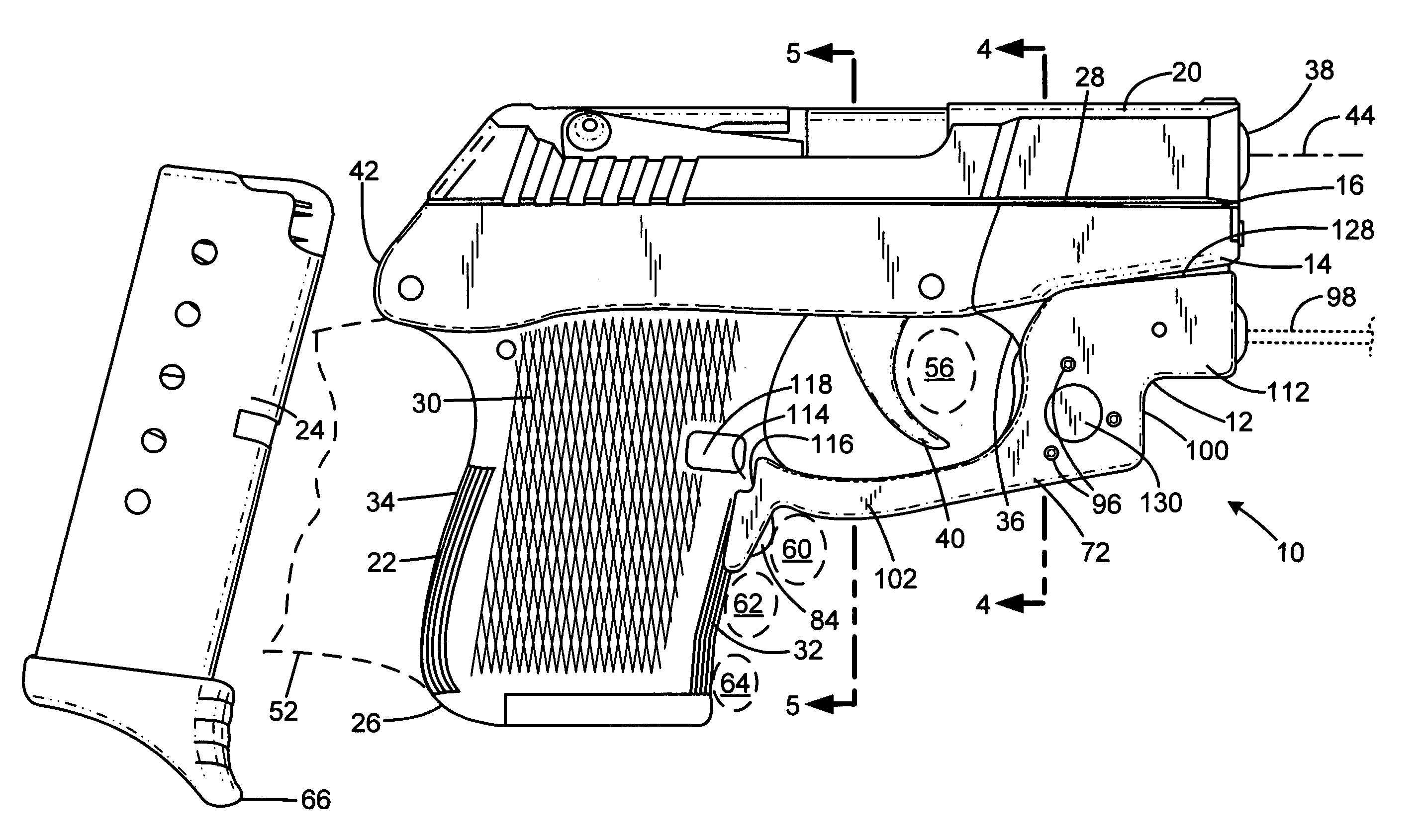
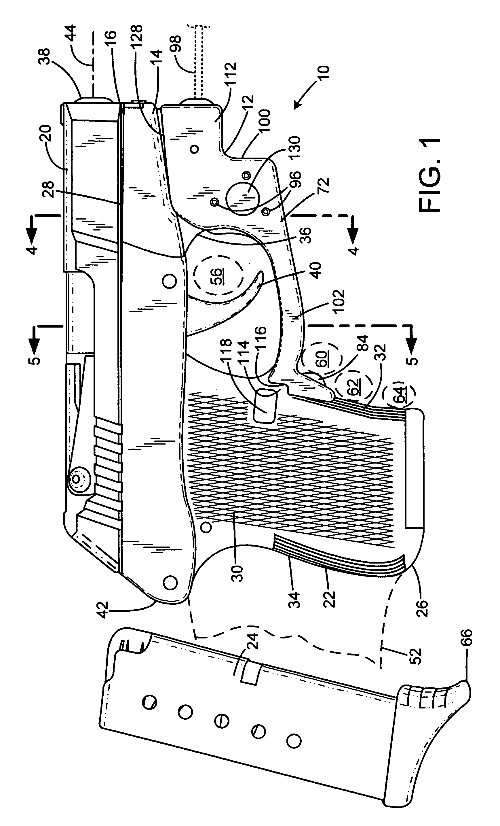
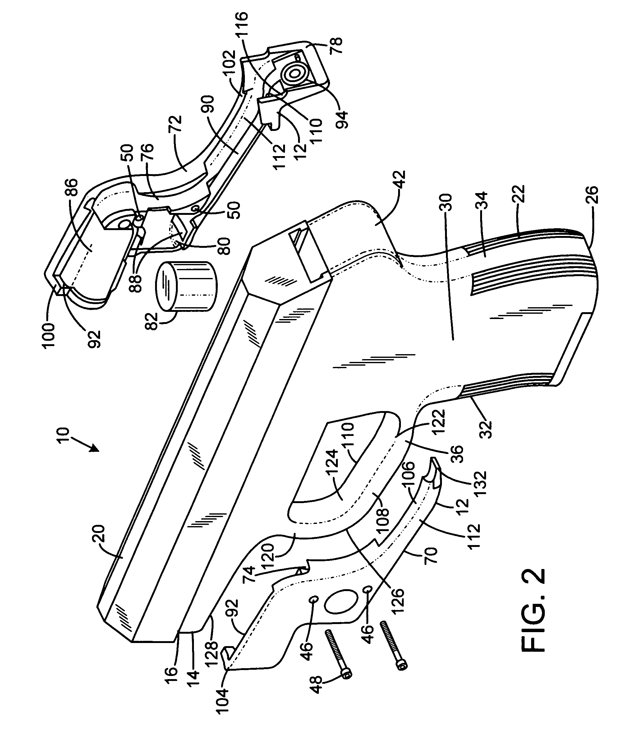
[0020]FIG. 1 shows a firearm 10 with an attached laser aiming device 12. The pistol has a one-piece integrally molded plastic frame 14 that includes an upper edge 16 immediately below the lower edge 28 of a slide 20 that reciprocates with respect to the pistol during chambering of cartridges and ejection of casings. The slide includes a barrel 38 having a barrel axis 44. Note that the device may be employed on any type of pistol or firearm in addition to those with integrally-molded frames, including any firearm having the conventional configuration of a grip adjacent to a trigger surrounded by a trigger guard.

[0021]The frame has a downwardly-extending handgrip 22 that angles slightly rearward and is a tubular body defining a well receiving a magazine 24. The handgrip has a lower free end 26. The grip has flat side portions 30, a curved front strap 32 facing forward, and a curved back strap 34 facing rearward. The grip generally has an oblong or “racetrack” cross section. At the upp...


PUM


Abstract

The present invention provides a sighting device for a firearm having a trigger guard, a frame with an underside portion forward of the trigger guard, and a handgrip with a front strap. The sighting device has a body having a first portion including an illumination device. The body defines an engagement feature operable term the bubbly connectivity for portion of the trigger guard. The body has an elongated extension portion that extends from the first portion. The extension portion is shaped to underlie a lower portion of the trigger guard from the first portion to the front strap. The extension portion has a free end including a switch, and the extension portion includes a conductor operably connecting the switch to the illumination device.

Description

FIELD OF THE INVENTION[0001]This invention relates to a laser gunsight system designed to fit the trigger guard of a firearm without requiring significant modification of the firearm, the laser gunsight being operable by the user while the firearm is gripped by the handgrip in the firing position.BACKGROUND AND SUMMARY OF THE INVENTION[0002]When using firearms, it is often advantageous for the user to be able to quickly and accurately point the firearm at the target. Many devices assisting in the aiming of a firearm are available, including the classic V-sight, peephole sight, 3-dot sight and similar iron-sight structures, as well as telescopic or optical sights. However, when light conditions are poor, such as at night or in darkened rooms of buildings, a sighting device that relies on ambient light is at a disadvantage. Under such conditions, the target may itself be difficult to acquire visually and to follow if it is moving, and gunsights that are lit only by external light sour...

Claims


Application Information

Patent Timeline
Patent Type & Authority Patents(United States)
IPC IPC(8): F41G1/35
CPCF41G1/35F41A19/11
Inventor DANIELSON, LEWIS A.HUGHES, DANIEL LEE
Owner CRIMSON TRACE
Why Eureka
Try Eureka