Sealed electrical splice assembly

a technology of electrical splicing and assembly, which is applied in the direction of securing/insulating coupling contact members, line/current collector details, coupling device connections, etc., can solve the problems of expensive manufacture and difficult packaging in some applications

Inactive Publication Date: 2012-09-04
DELPHI TECH INC
View PDF12 Cites 36 Cited by
  • Summary
  • Abstract
  • Description
  • Claims
  • Application Information

AI Technical Summary

Benefits of technology

[0006]In accordance with one embodiment of the invention, a sealed electrical splice assembly includes a housing defining a cavity and including an opening. A conductive bus plate is retained in the cavity. A plurality of electrically conductive terminals are received in the cavity are electrically connected to the bus plate. A seal plug is disposed in the cavity through the opening adapted to sealingly engage an...

Problems solved by technology

Consequently, such joint connectors may be complicated, expensive to m...

Method used


Image

  • Sealed electrical splice assembly
  • Sealed electrical splice assembly
  • Sealed electrical splice assembly

Examples


Embodiment Construction

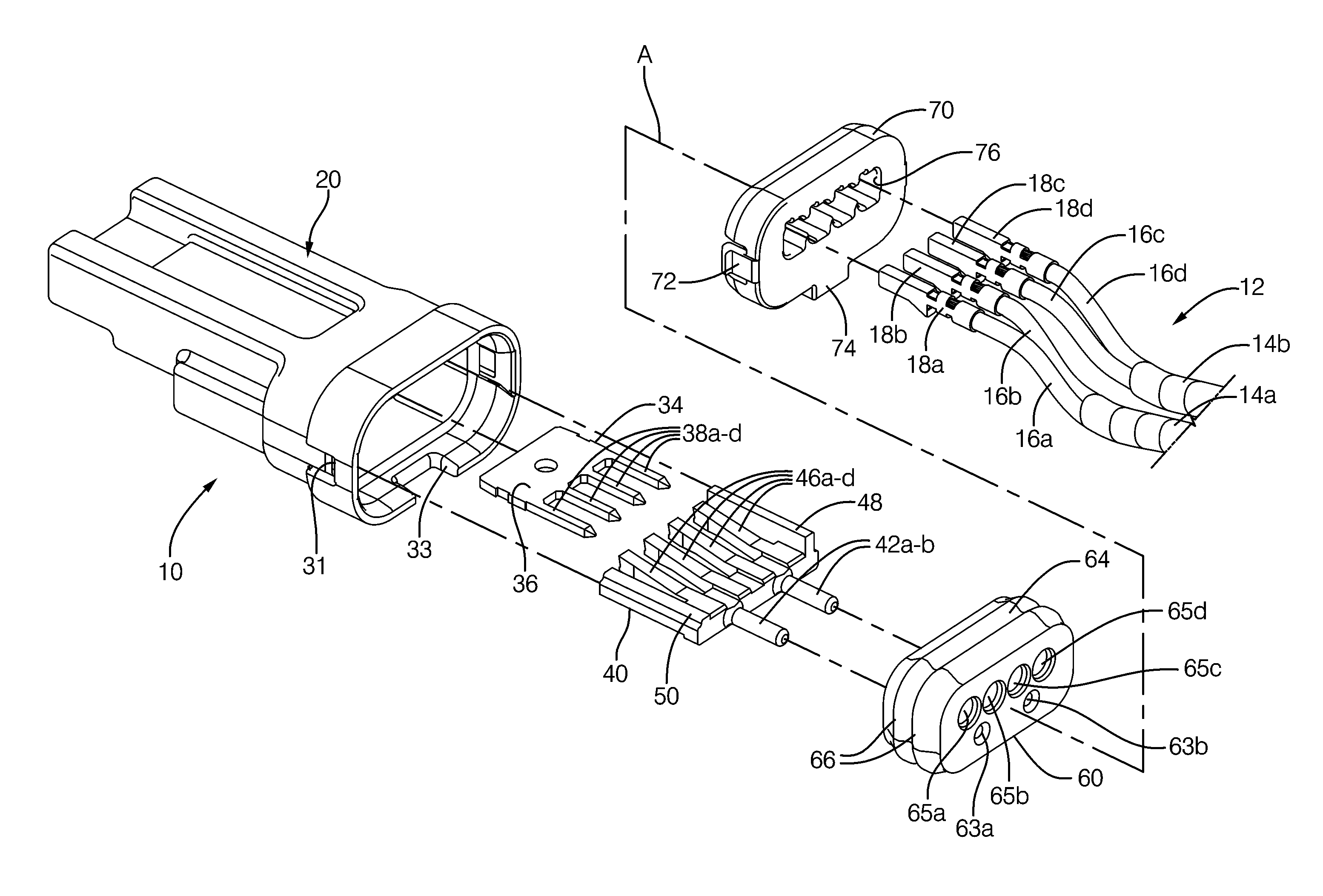
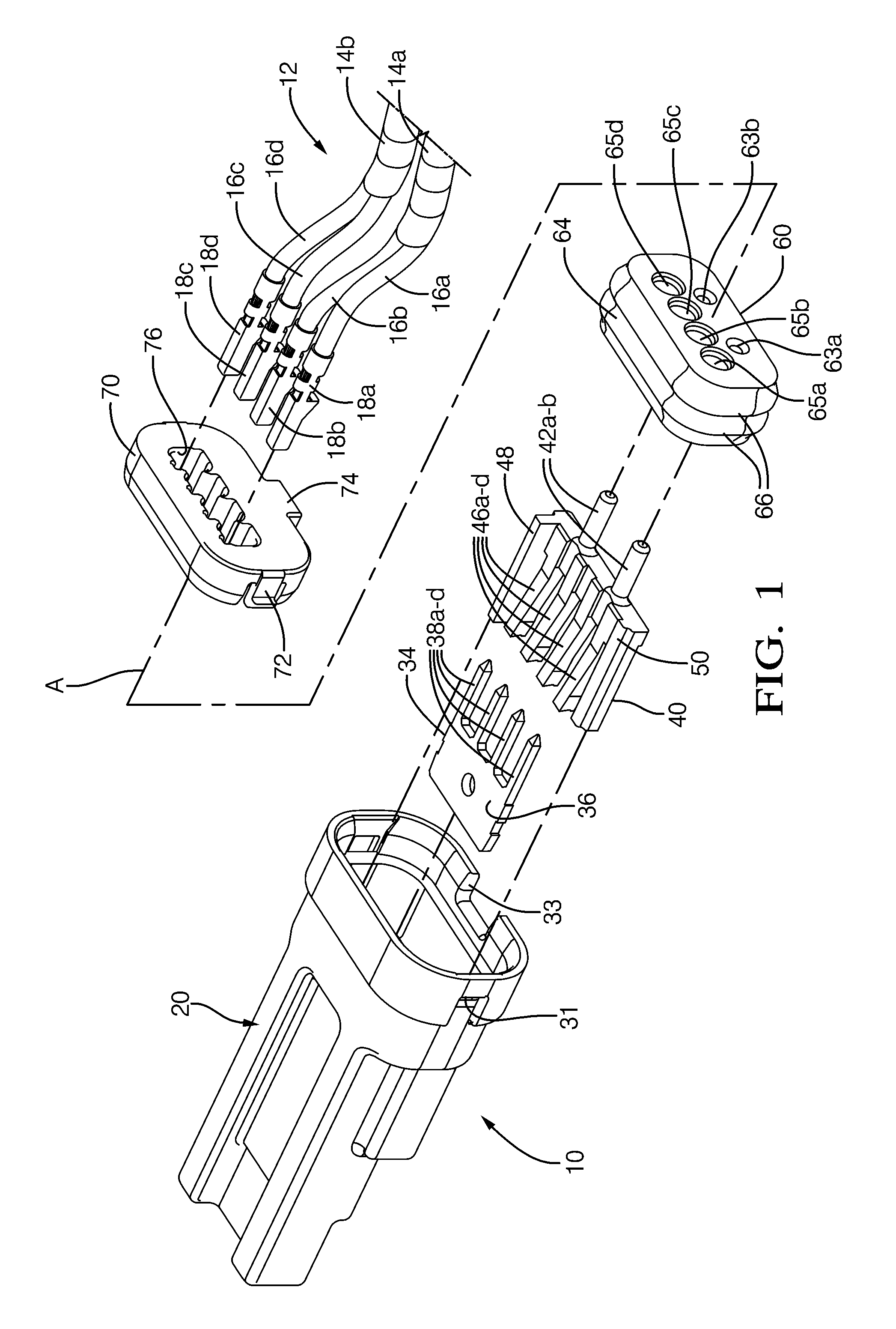
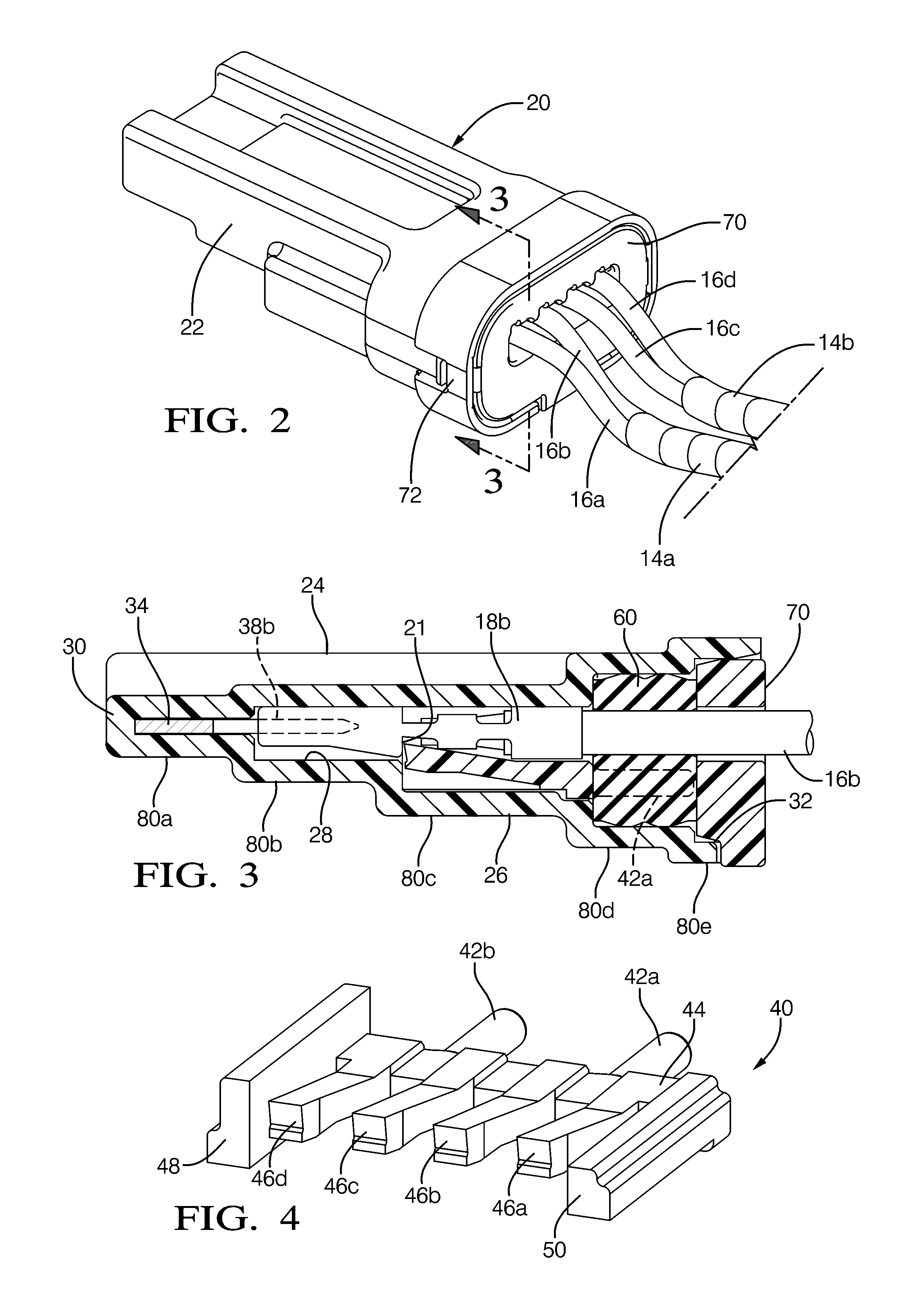
[0017]Referring to FIGS. 1 and 2, in accordance with the embodiments of this invention, a sealed electrical splice assembly 10 is used in the manufacture of a cable harness 12. Cable harness 12 electrically connects together electrical components disposed in a vehicle (not shown). Cable harness 12 includes a pair of branch cables 14a, 14b. Each respective branch cable 14a, 14b includes wiring assemblies having electrical connections. The wiring assemblies include a plurality of wire cables, or conductors 16a-d being connected to a plurality of corresponding electrically conductive female box terminals 18a-d. Female terminals 18a-d are inserted in assembly 10 along a mating axis A so that assembly 10 is used to electrically connect an electrical signal carried on one wire conductor of wire conductors 16a-d of cable harness 12 to the other remaining wire conductors disposed in assembly 10. For example and not limitation, the electrical signal on wire conductor 16a and terminal 18a may...


PUM

PropertyMeasurementUnit
Electrical conductivityaaaaaaaaaa
Flexibilityaaaaaaaaaa
Electrical conductoraaaaaaaaaa

Abstract

A sealed electrical splice assembly includes a housing defining a cavity and including an opening. A conductive bus plate is retained in the cavity. A plurality of electrically conductive terminals are received in the cavity are electrically connected to the bus plate. The plurality of terminals are connected to a plurality of wire conductors. A seal plug is disposed in the cavity through the opening adapted to sealingly engage an interior surface of the housing surrounding the seal plug. An end cover overlies the seal plug disposed in the opening. The cavity receives the plurality of terminals through the end cover and the seal plug thereby allowing the seal plug to sealingly engage the plurality of wire conductors.

Description

RELATED DOCUMENTS TO APPLICATION[0001]This application is related to U.S. Application U.S. Ser. No. 12 / 723,741 filed 15 Mar. 2010 having the title “SPLICE ASSEMBLY”, which is co-owned by the assignee of this application, and incorporated by reference herein.TECHNICAL FIELD[0002]This invention relates to electrical splice assemblies used in cable harnesses.BACKGROUND OF INVENTION[0003]It is known to use joint connectors, for example, in automotive splice applications in which a centralized connector is needed to connect one or more main wire cables to a plurality of branching wire cables.[0004]Such joint connectors typically comprise many component parts, such as a housing, terminals, bus bars, a cover, and the like. Consequently, such joint connectors may be complicated, expensive to manufacture, and bulky, making them difficult to package in some applications. Joint connectors may also be required to be disposed in automotive applications where exposure to environmental elements su...

Claims


Application Information

Patent Timeline
IPC IPC(8): H01R13/40
CPCH01R13/5208H01R43/005H01R31/085Y10T29/49174
Inventor SMUTNY, DALE J.WEBER, WESLEY W.
Owner DELPHI TECH INC
Why Eureka
Try Eureka