RFID reader with sub-orthogonal self-jammer cancellation

a technology of rfid reader and self-jammer, which is applied in the field of rfid reader with suborthogonal self-jammer cancellation, can solve the problems of degrading the quality or unintended operations of the reader, attenuating the already weak rfid tag signal, etc., and achieves the effect of reducing the amplitude of the rf signal

Active Publication Date: 2012-09-04
IMPINJ
View PDF3 Cites 20 Cited by
  • Summary
  • Abstract
  • Description
  • Claims
  • Application Information

AI Technical Summary

Benefits of technology

[0009]Embodiments are directed to a sub-orthogonal self-jammer cancellation circuit adapted to receive a self-jamming signal associated with the transmit signal and generate at least two distinct phase variants of the transmit signal. The sub-orthogonal self-jammer circuit may select two of the distinct phase variants, where a vector projection of a first of the selected phase variants on a second of the selected phase variants is substantially greater than zero, and a canceling signal comprising a combination of the selected phase variants is substantially opposite in phase to the self-jamming signal. According to some embodiments, the sub-orthogonal self-jammer circuit may also select amplitudes for each of the two phase variants such that the canceling signal is substantially equal in amplitude to the self-jamming signal and combine the canceling signal with the self-jamming signal to reduce the amplitude of the RF signal received by the receive circuit.

Problems solved by technology

Because the RF signals transmitted by the RFID tags (in response to the RF signal transmitted by the reader) are relatively weak signals, the self-jammer signal may interfere with the RF signals received from the tags causing degradation of quality or unintended operations at the reader.
One approach to mitigating the self-jammer signal is attenuating a received signal at the RFID reader's front end through resistive or similar components, but that would also attenuate the already weak RFID tag signals, and is therefore an undesirable solution.

Method used


Image

  • RFID reader with sub-orthogonal self-jammer cancellation
  • RFID reader with sub-orthogonal self-jammer cancellation
  • RFID reader with sub-orthogonal self-jammer cancellation

Examples


Embodiment Construction

[0025]In the following detailed description, references are made to the accompanying drawings that form a part hereof, and in which are shown by way of illustration specific embodiments or examples. These embodiments or examples may be combined, other aspects may be utilized, and structural changes may be made without departing from the spirit or scope of the present disclosure. The following detailed description is therefore not to be taken in a limiting sense, and the scope of the present invention is defined by the appended claims and their equivalents.

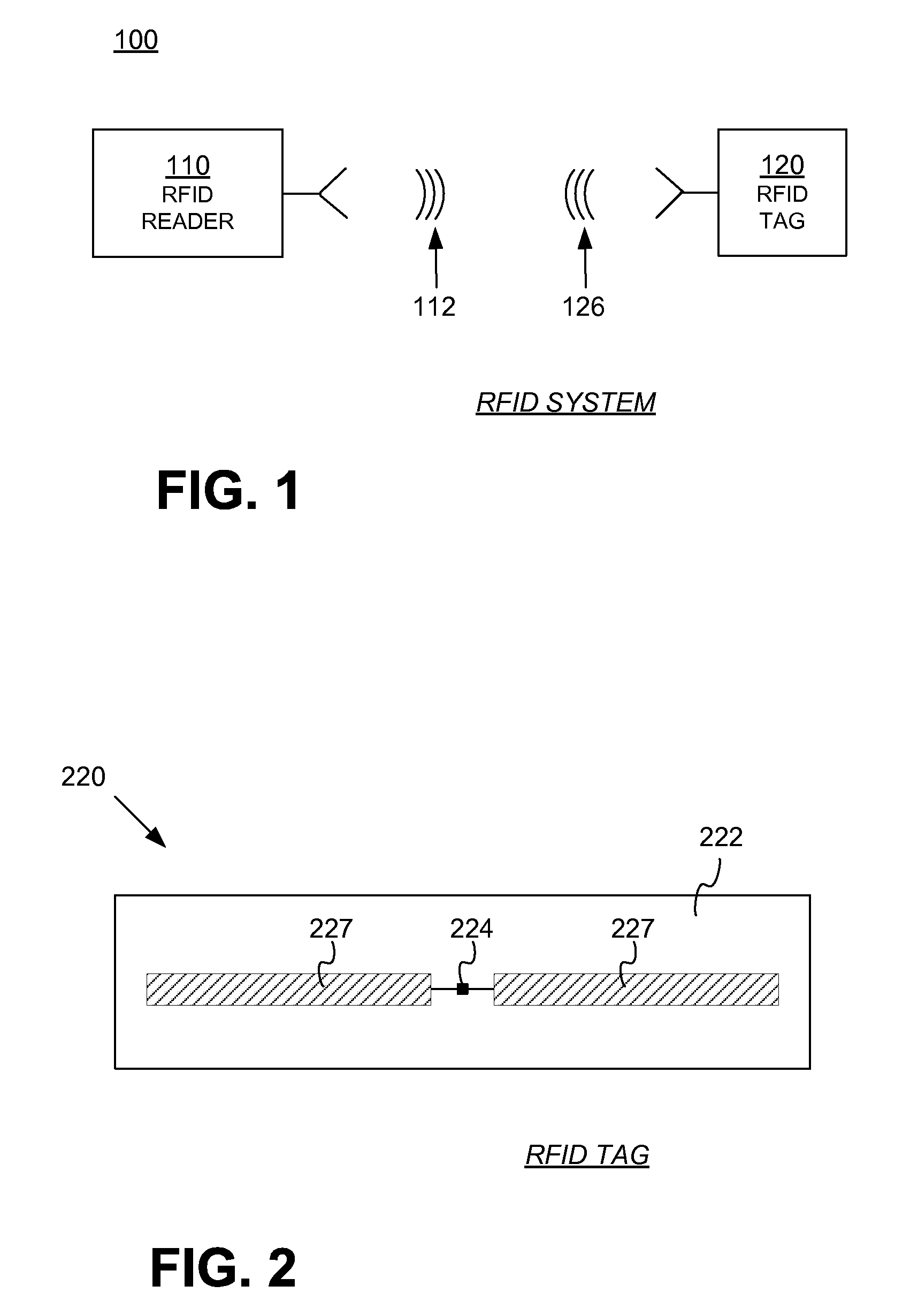
[0026]FIG. 1 is a diagram of components of a typical RFID system 100, incorporating embodiments. An RFID reader 110 transmits an interrogating Radio Frequency (RF) wave 112. RFID tag 120 in the vicinity of RFID reader 110 may sense interrogating RF wave 112 and generate wave 126 in response. RFID reader 110 senses and interprets wave 126.

[0027]Reader 110 and tag 120 exchange data via wave 112 and wave 126. In a session of such an e...


PUM


Abstract

RFID readers configured to transmit a radio frequency signal include a sub-orthogonal self-jammer cancellation circuit that generates two or more distinct phase variants of the transmit signal, selects two of the phase variants with a vector projection of one of the selected phase variants on another of the selected phase variants being substantially greater than zero such that a canceling signal comprising a combination of the at least two phase variants is substantially opposite in phase to a self-jamming signal, and selects amplitudes for the at least two selected phase variants such that the canceling signal is substantially equal in amplitude to the self-jamming signal. The canceling signal is then combined with the self-jamming signal to reduce the amplitude of an RF signal received by a receive circuit.

Description

CROSS REFERENCE TO RELATED APPLICATIONS[0001]This application claims the benefit of U.S. Provisional Patent Application Ser. No. 61 / 257,774 filed on Nov. 3, 2009. The disclosures of the provisional patent application are hereby incorporated by reference for all purposes.BACKGROUND[0002]Radio Frequency Identification (RFID) systems typically include RFID tags and RFID readers. RFID readers are also known as RFID reader / writers or RFID interrogators. RFID systems can be used in many ways for locating and identifying objects to which the tags are attached. RFID systems are particularly useful in product-related and service-related industries for tracking objects being processed, inventoried, or handled. In such cases, an RFID tag is usually attached to an individual item, or to its package.[0003]In principle, RFID techniques entail using an RFID reader to interrogate one or more RFID tags. The reader transmitting a Radio Frequency (RF) wave performs the interrogation. The RF wave is ty...

Claims


Application Information

Patent Timeline
Patent Type & Authority Patents(United States)
IPC IPC(8): H04B1/10H04B7/00
CPCH04B1/525G06K7/10158
Inventor HYDE, JOHN D.
Owner IMPINJ
Why Eureka
Try Eureka