Stackable plant pot

a plant pot and spherical technology, applied in the field of stackable plant pots, can solve the problems of unsuitable use, unadaptable arrangement of plant pots, and complex design and construction of individual pots, and achieve the effect of preventing the build-up of unwanted surplus drainage and easy removal

Inactive Publication Date: 2012-09-11
STACKAPOTS PTY LTD
View PDF35 Cites 8 Cited by
  • Summary
  • Abstract
  • Description
  • Claims
  • Application Information

AI Technical Summary

Benefits of technology

[0016]The water catchment region is laterally defined by a side wall or walls of a downward formed recess centrally located in the bottom of the plant pot cavity, within the laterally aligned bottom wall of recessed catchment region is a series of depressions forming gutters with each gutter supporting a plurality of time controlled water flow inhibiting drainage holes. Said time controlled water flow inhibiting drainage holes are narrowed slits through the wall of these catchment region drainage gutters allowing a timely inhibited transfer of excess water to escape the catchment region in order to allow the moisture retaining mat working in co-operation with the plant pot sufficient time to fully absorb to the extent of its capability the maximum amount of storable water.
[0019]The moisture mat provided may be constructed of any substance or materials that possess super absorbent properties and is provided with an outer skin that has excellent moisture transferring qualities.
[0021]The fine grade Potassium Cross-linked Acrylamide Acrolith Co-polymer Gel Crystals are super absorbent and can swell to 200 to 400 times their dry state with stored water. The moisture mat will be provided with an add rate of these of fine grade Potassium Cross-linked Acrylamide Acrylate Co-polymer Gel Crystals to exactly expand the moisture retaining mat to a depth of the recessed centrally located water catchment region with stored water and as a result provide an enormous expanse of moisture transferring surface spanning the entire water catchment area.
[0030]Typically this saucer plate will have water retaining capabilities suited for indoor gardening however the saucer plate has easily removable blind drainage holes and will allow full drainage to suit gardening outdoors and prevent the build up of unwanted surplus drainage that may encourage mosquito breeding.

Problems solved by technology

Generally, however, such plant pots can not be stacked-one on top of another-in any suitable manner for use.
Also, this arrangement of plant pots is not adapted to be hung or suspended.
Also, the particular design and construction of each individual pot is quite complex and it would be difficult and expensive to manufacture.
The plant pot of this disclosure is relatively flimsy and the stacking of 3 or more plant pots (especially if they contain soil) is likely to cause the lower pots in the arrangement to collapse or deform.
This arrangement for connecting adjacent pots is awkward for a user, given the relatively small sizes of the corresponding protrusions and slots.
One of the deficiencies in this prior art is that there is no provision in each plant pot to specifically direct the flow of water to the reservoir region and in effect water may pass by the water reservoir region and through the overflow drainage holes not filling the reservoir region efficiently if at all.
Usually these means work very favourably for small pots however with larger pots wicks have been found to be very ineffective providing insufficient surface area of moisture transferal for the larger volume of soil to draw upon via the soils own capillary action.
One further deficiency found accordingly unless the stackable plant pots when positioned in their stacked formation are perfectly perpendicular portions of the radially extending sections of the water reservoir area may never fill and render the wicks in these portions less effective or useless.

Method used


Image

  • Stackable plant pot
  • Stackable plant pot
  • Stackable plant pot

Examples


Embodiment Construction

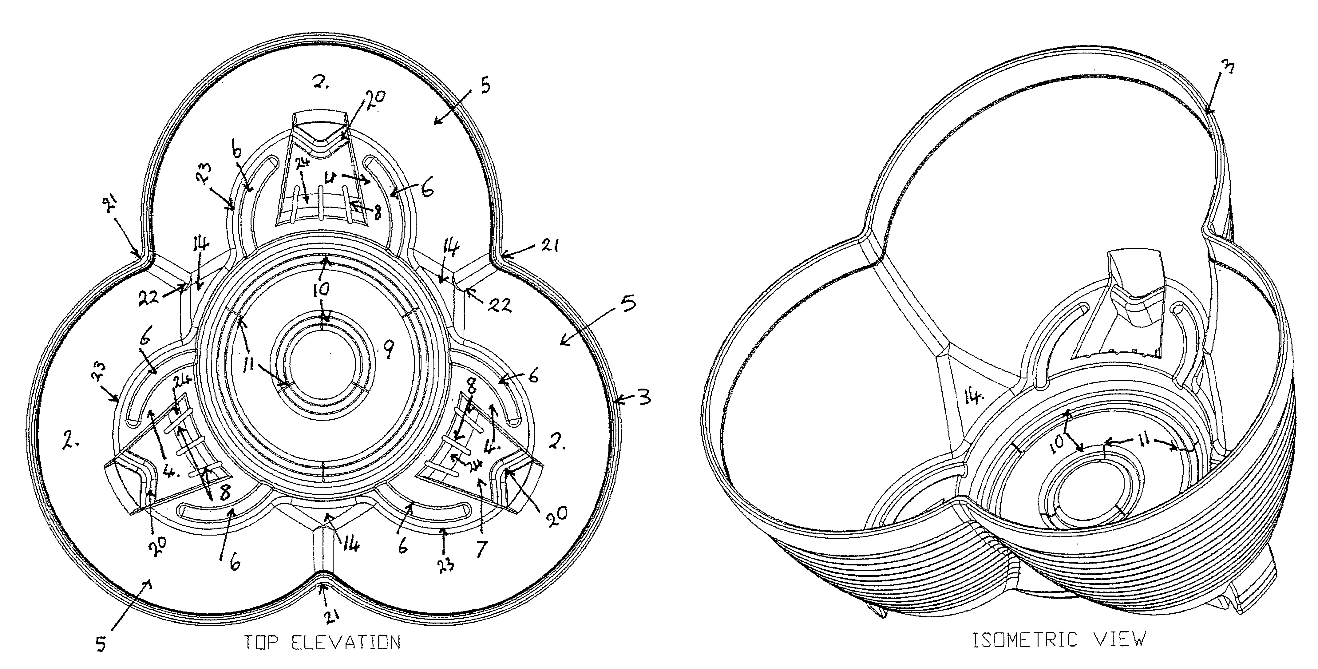
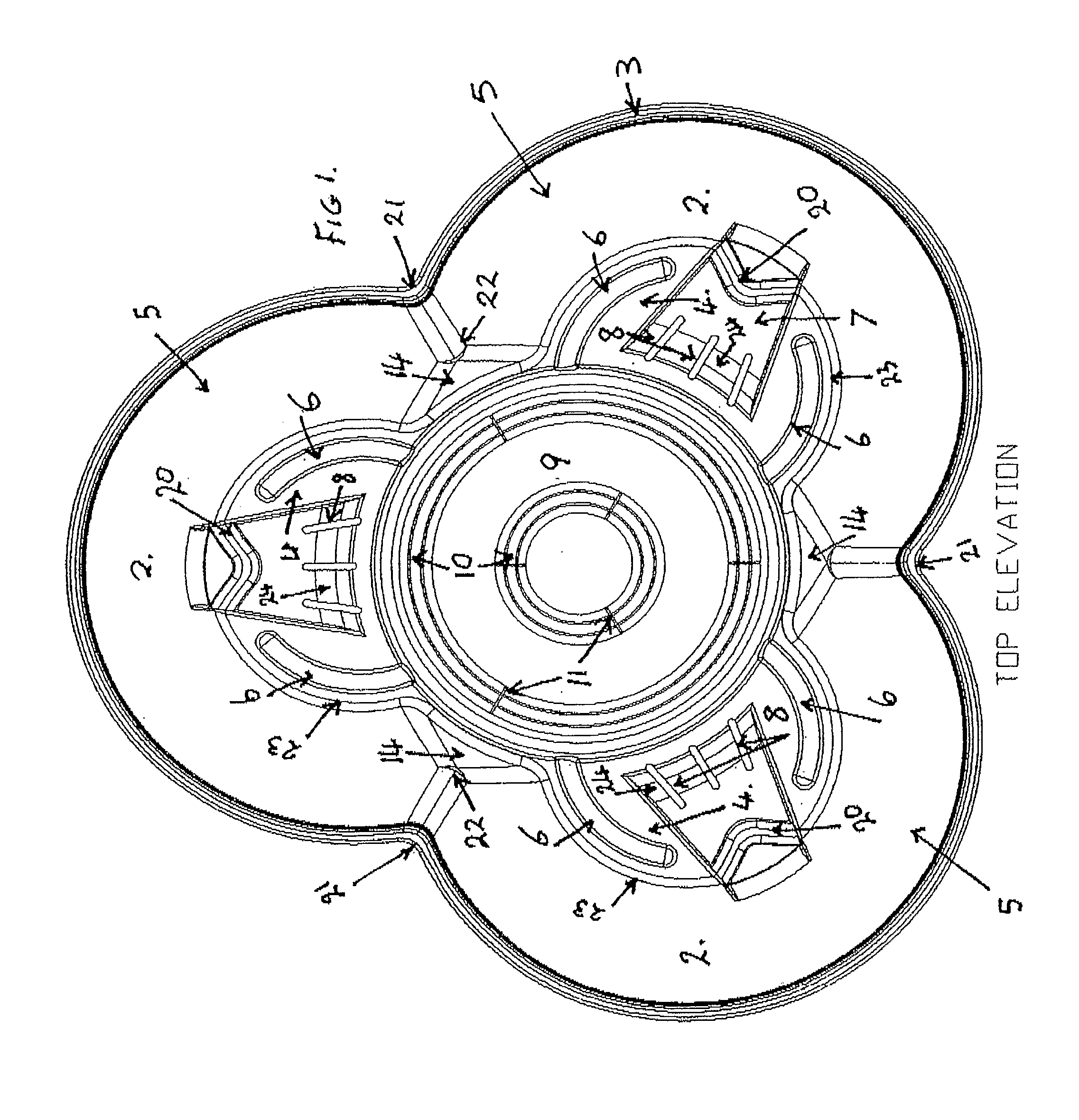
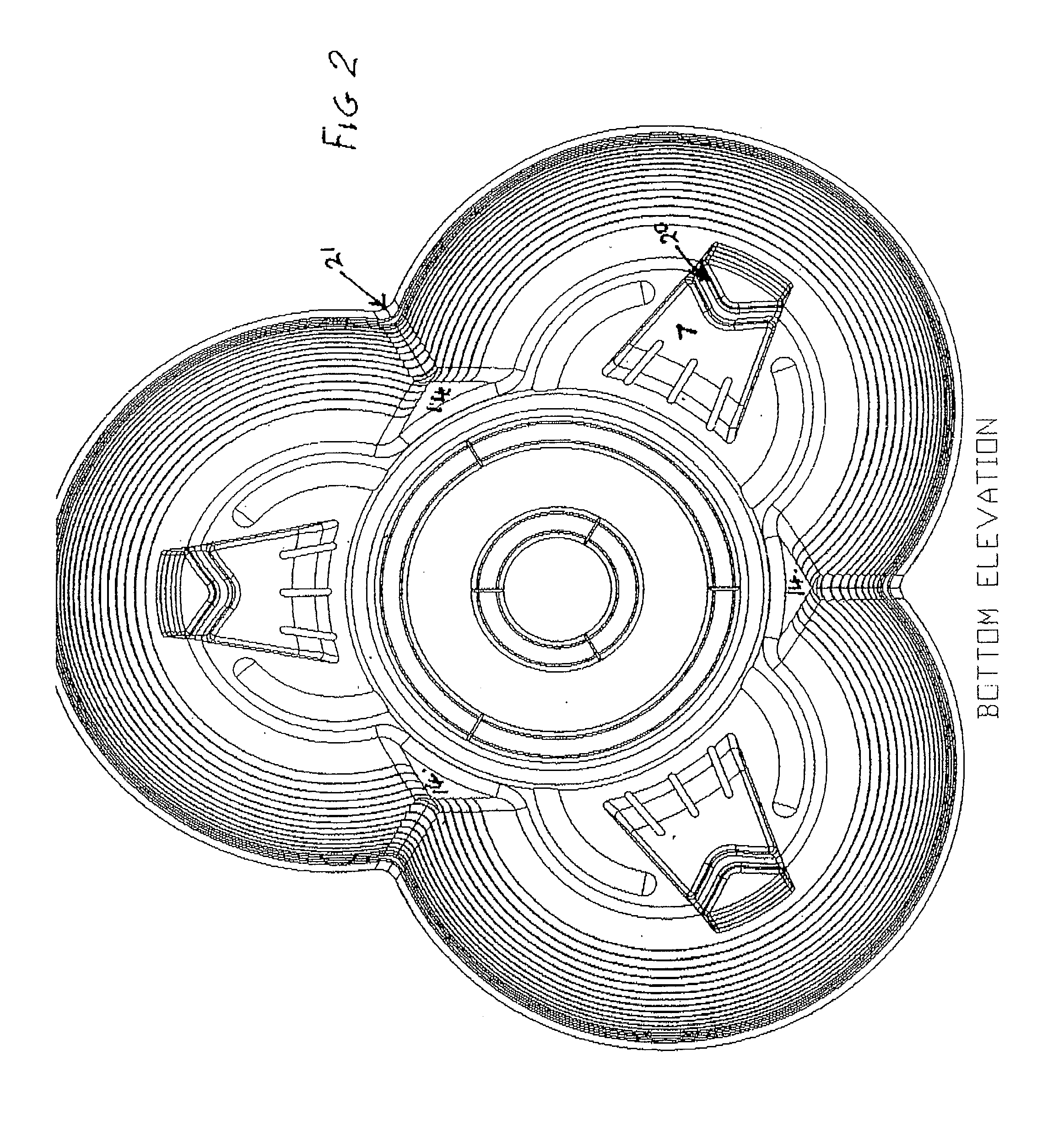
[0054]As shown in the diagrams, particularly FIGS. 1 and 2, of the present invention includes a plant pot which, in use, is adapted to be stacked with one or more similar plant pots, said plant pot comprising: a cavity depicted in FIG. 1 with three radially located lobed sub-cavity sections 2 with thickened rim 3 a base portion 4 and side walls 5 a series of water flow directing gutters 6, also referred to as primary water flow directing gutters 6, interconnecting pot leg structures 7 with rapid release drainage holes 8, also referred to as secondary drainage outlet 8, a centrally located water catchment region 9, provided with further water flow directing gutters 10, also referred to as secondary water flow directing gutters 10, and time controlled water flow inhibited excess water drainage slits 11, also referred to as primary drainage outlet 11, a moisture retaining mat working 13 A and B of FIG. 9 in co-operation with the plant pot as shown in FIGS. 9A and 19A B and C and a soil...


PUM


Abstract

A stackable plant pot including a cavity provided with water flow directing gutters, a recesses centrally located water catchment region with drainage slits and suited to receive a moisture retaining device, and a soil holding region located above the water catchment region.

Description

TECHNICAL FIELD[0001]The present invention relates to a stackable plant pots and, in particular to a stackable plant pot.BACKGROUND[0002]Various forms of plant pots are known for growing plants. Typical plant pots are either of generally cylindrical, frustoconical or rectangular prism form. Frustoconical type plant pots, or other plant pots which are tapered so that the bottom of each pot is narrower than the top, are advantageous over cylindrical or rectangular prism type pots in that they are often able to be located at least partially within each other and thereby able to be stacked for transport, storage and display, thereby realising considerable space savings. Generally, however, such plant pots can not be stacked-one on top of another-in any suitable manner for use. Many pot plant enthusiasts like to arrange several pots in a generally vertical relationship for particular aesthetic appeal and saving of space. Such an arrangement currently typically depends on use of a separat...

Claims


Application Information

Patent Timeline
Patent Type & Authority Patents(United States)
IPC IPC(8): B65D85/50A01G9/02A01G25/00
CPCA01G9/023A01G9/02A01G9/022
Inventor KEATS, JOHN RODNEY
Owner STACKAPOTS PTY LTD
Why Eureka
Try Eureka