
Tube pump and rotor for tube pump

a tube pump and rotor technology, which is applied in the direction of machines/engines, flexible member pumps, positive displacement liquid engines, etc., can solve the problems of easy increase the cost, so as to reduce the pulsation and load, prevent the malfunction of the tube pump, and reduce the cost

Active Publication Date: 2012-09-11
JMS CO LTD
View PDF17 Cites 1 Cited by
  • Summary
  • Abstract
  • Description
  • Claims
  • Application Information

AI Technical Summary

Benefits of technology

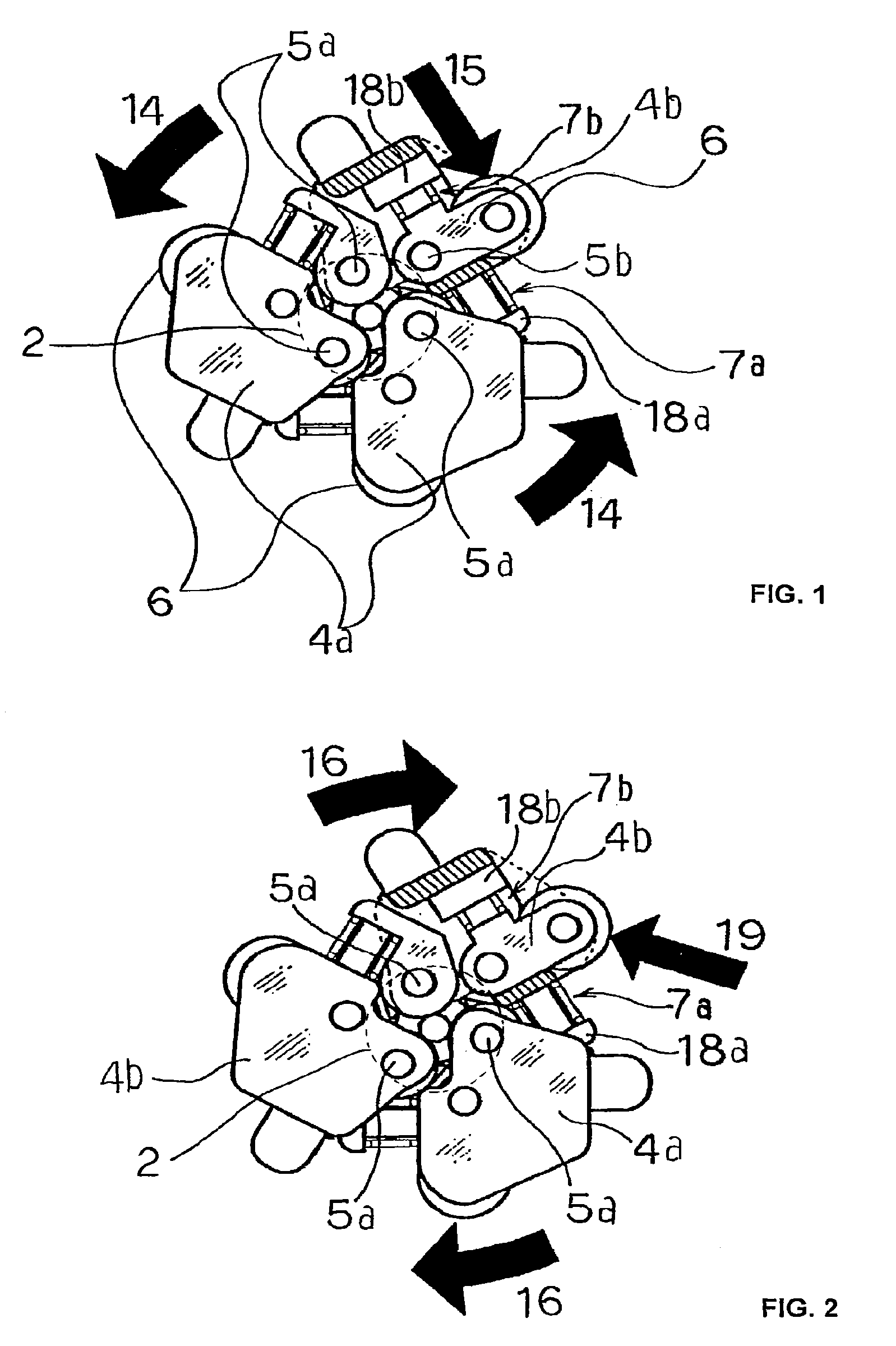
[0009]In known tube pumps of the type shown in FIG. 6, wherein liquid can be sucked into and exhausted from the resilient tube even if the rotor element 2 is rotated in a reverse direction (clockwise direction) 16, a load 17 having pulsations in a direction across the direction 15 in which the load is reduced by the buffer member 7 is applied to the roller 6 when the rotor element 2 is rotated in the reverse direction 16, so that the load 17 including the pulsations cannot be reduced by the buffer member 7. Accordingly, it is necessary to increase the strength of the housing or the motor of the tube pump, if the rotor element 2 of the tube pump is rotated in the reverse direction for a long time.
[0010]Further, in case that the tube pump wherein the rotor element is rotated in the normal direction is changed to a tube pump wherein the rotor element is rotated in the reverse direction, the parts or the assembling manner of the tube pump must be changed, such that the cost is increased and a malfunction of the tube pump may occur easily.
[0016]The rotor for the tube pump of the present invention can be applied to the tube pump wherein the rotor is rotated not only in the normal direction, but also in the reverse direction, so as to reduce the pulsations and the load, and to run the tube pump for a long time.
[0017]Further, in the case where the rotor of the present invention is used for each of a plurality of tube pumps, each rotated in different directions, the same parts and assembling manner can be used, such that the cost may be reduced and the malfunction of the tube pump may be prevented.

Problems solved by technology

Further, in case that the tube pump wherein the rotor element is rotated in the normal direction is changed to a tube pump wherein the rotor element is rotated in the reverse direction, the parts or the assembling manner of the tube pump must be changed, such that the cost is increased and a malfunction of the tube pump may occur easily.

Method used


Image

  • Tube pump and rotor for tube pump
  • Tube pump and rotor for tube pump
  • Tube pump and rotor for tube pump

Examples


Embodiment Construction

[0053]Embodiments of the present invention will now be explained with reference to the drawings.

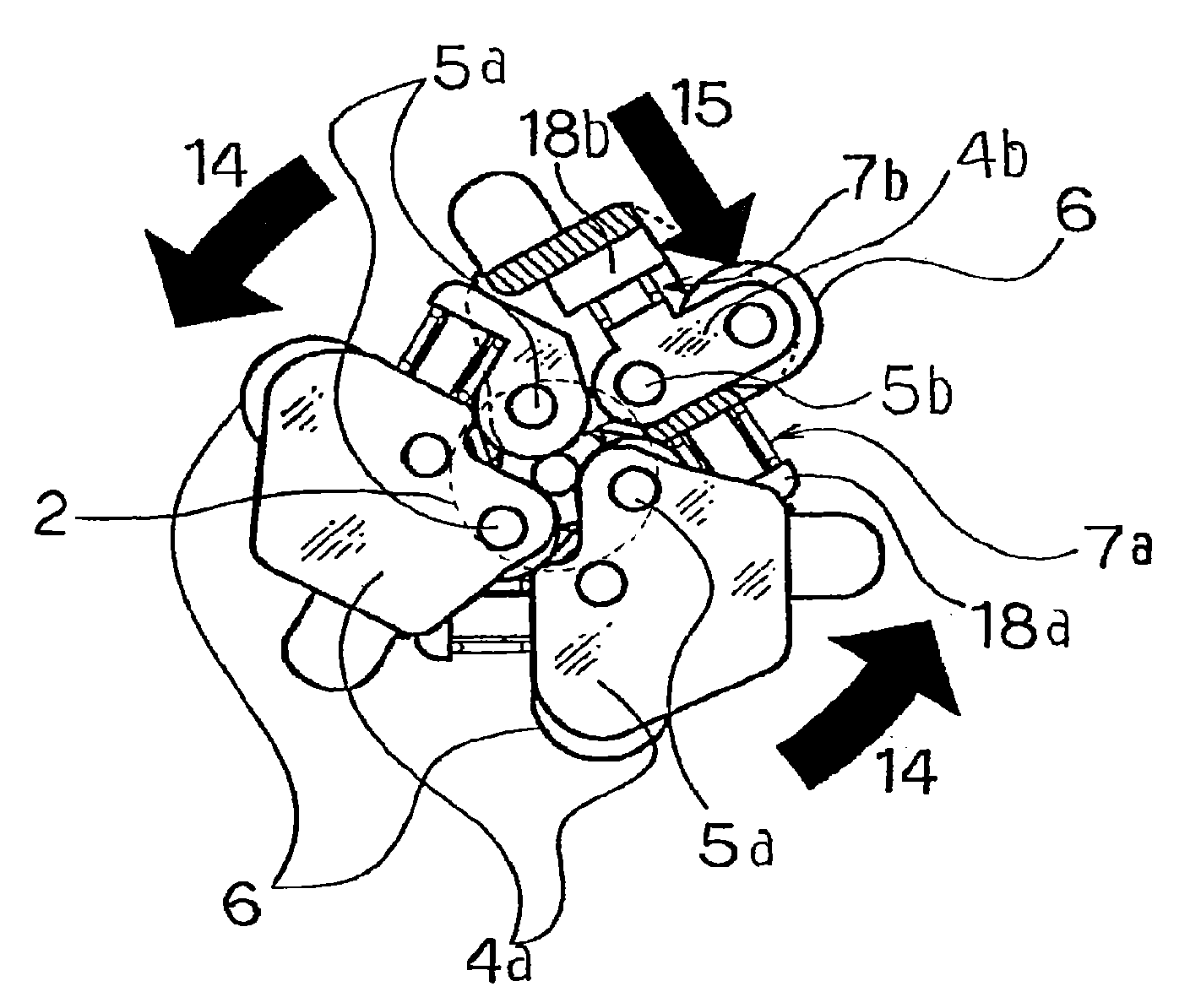
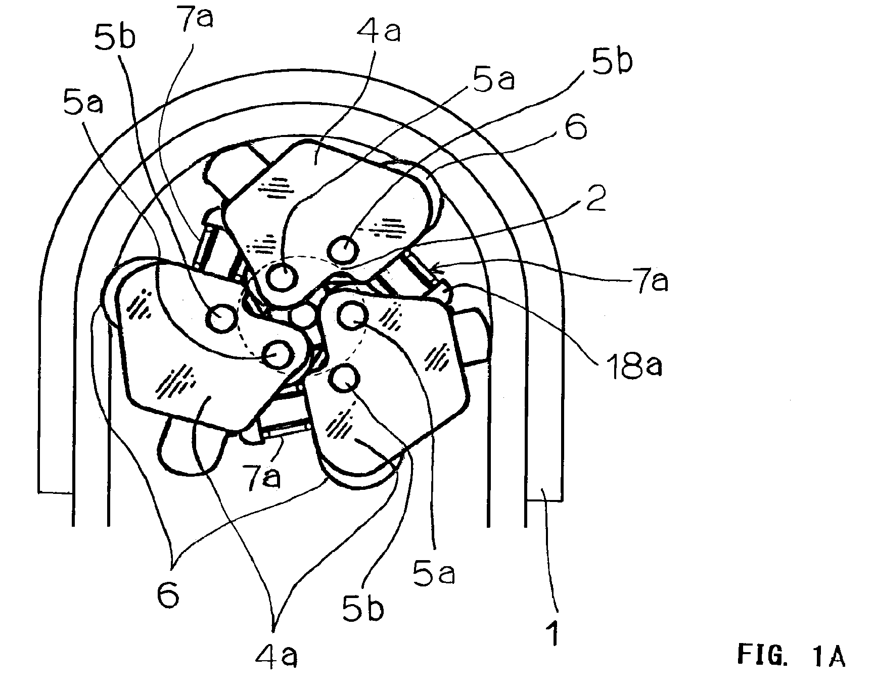
[0054]A rotor for a tube pump in a first embodiment of the present invention comprises, as shown in FIG. 1 and FIG. 2, a rotor element 2, a first of three swing portions 4a, each base end of which being supported rotatably through a shaft 5a at each of positions of the rotor element 2 equidistantly apart from one another by 120° on a circle, a second of three arm-shaped swing portion 4b, each base end of which being supported rotatably by the rotor element 2 through a shaft 5b at each of positions different from each of positions for the shaft 5a, receiving plates 18a, each mounted on the rotor element 2 so as to extend outwardly from the rotor element 2 and to face a side surface of each corresponding, first swing portion 4a, receiving plates 18b, each formed on each corresponding first swing portion 4a, buffer members 7a, each consisting of a spring and inserted between the receiving pl...


PUM


Abstract

A tube pump rotor including a rotor element, a plurality of first swing portions supported pivotally at their base end portions by the rotor element, second arm-shaped swing portions supported pivotally at their base end portions individually by the first swing portions, rollers supported rotatably by the individual free ends of the second swing portions, and buffer members made to confront the side faces of the second swing portions so that the rollers may be individually directed radially outward of the rotor.

Description

PRIORITY CLAIM[0001]The present application is a National Phase entry of PCT Application No. PCT / JP2008 / 052645, filed Feb. 18, 2008, which claims priority from Japanese Application No. 2007-039442, filed Feb. 20, 2007, the disclosures of which are hereby incorporated by reference herein in their entirety.TECHNICAL FIELD[0002]The present invention relates to a tube pump and a rotor for the tube pump, and more particularly, to a roller type tube pump and a rotor for the roller type tube pump.BACKGROUND[0003]Tube pumps required to be rotated in the normal and reverse directions are publicly known. In such a conventional tube pump, the rotor is rotated forcibly in the reverse direction without changing the mechanism thereof, because of the running time is short or the like. Several pumps of this same kind, but different in rotary direction from one another are also known.[0004]One commercially available tube pump is disclosed in the patent materials, for example, Japanese Patent Applica...

Claims


Application Information

Patent Timeline
Patent Type & Authority Patents(United States)
IPC IPC(8): F04B43/12F04B45/06
CPCF04B43/1253F04B43/1276
Inventor KOJIMA, SEIJISEKIYA, KOUFUJII, JUNYAKAMITO, SHOGO
Owner JMS CO LTD
Learn More