

Inertial weight for physical conditioning
a technology of inner-body weight and physical conditioning, applied in the field of inner-body weight for physical conditioning, can solve problems such as undesirable strain on the muscles
- Summary
- Abstract
- Description
- Claims
- Application Information
AI Technical Summary
Benefits of technology
Problems solved by technology
Method used
Image

Examples
Embodiment Construction
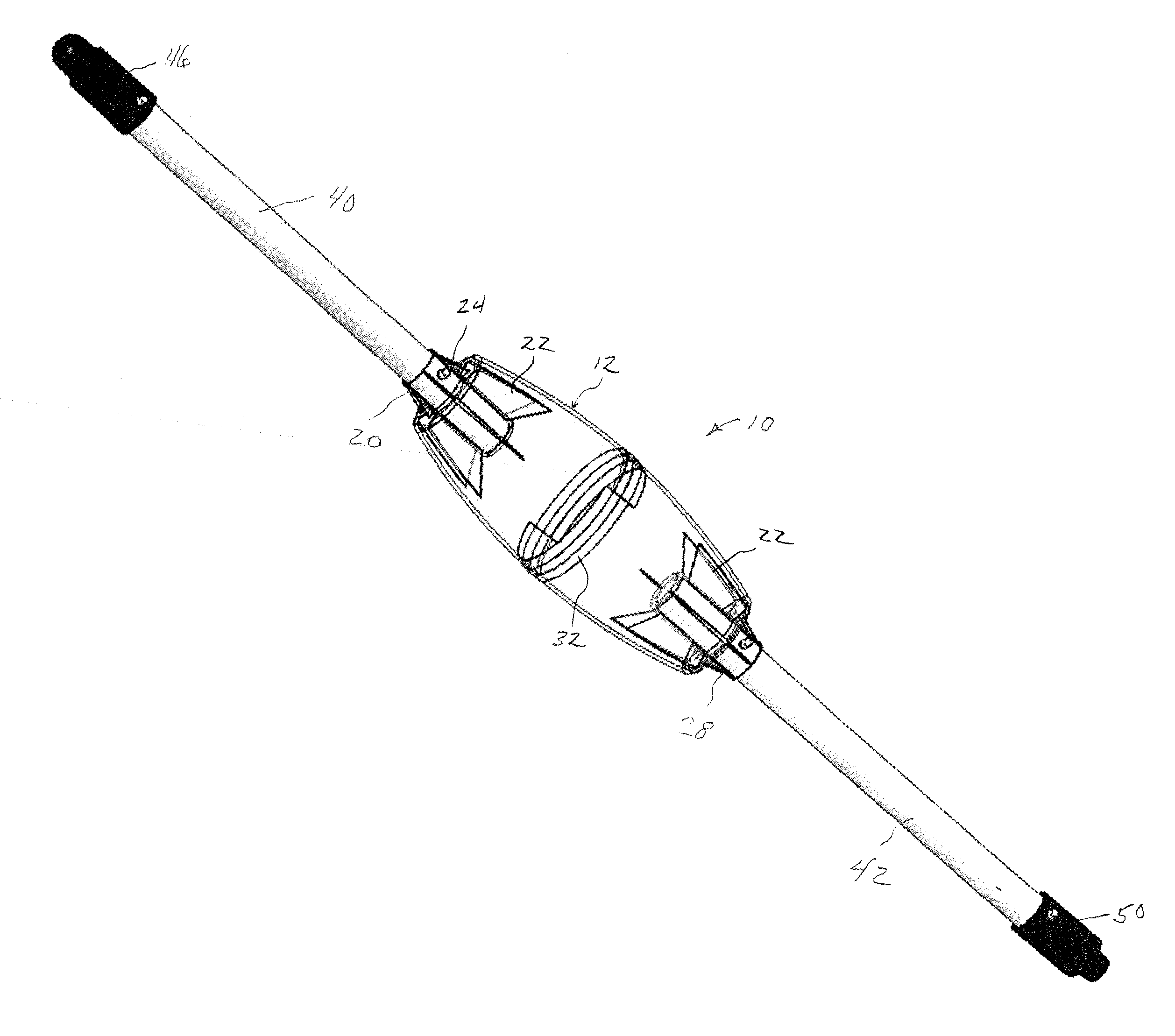
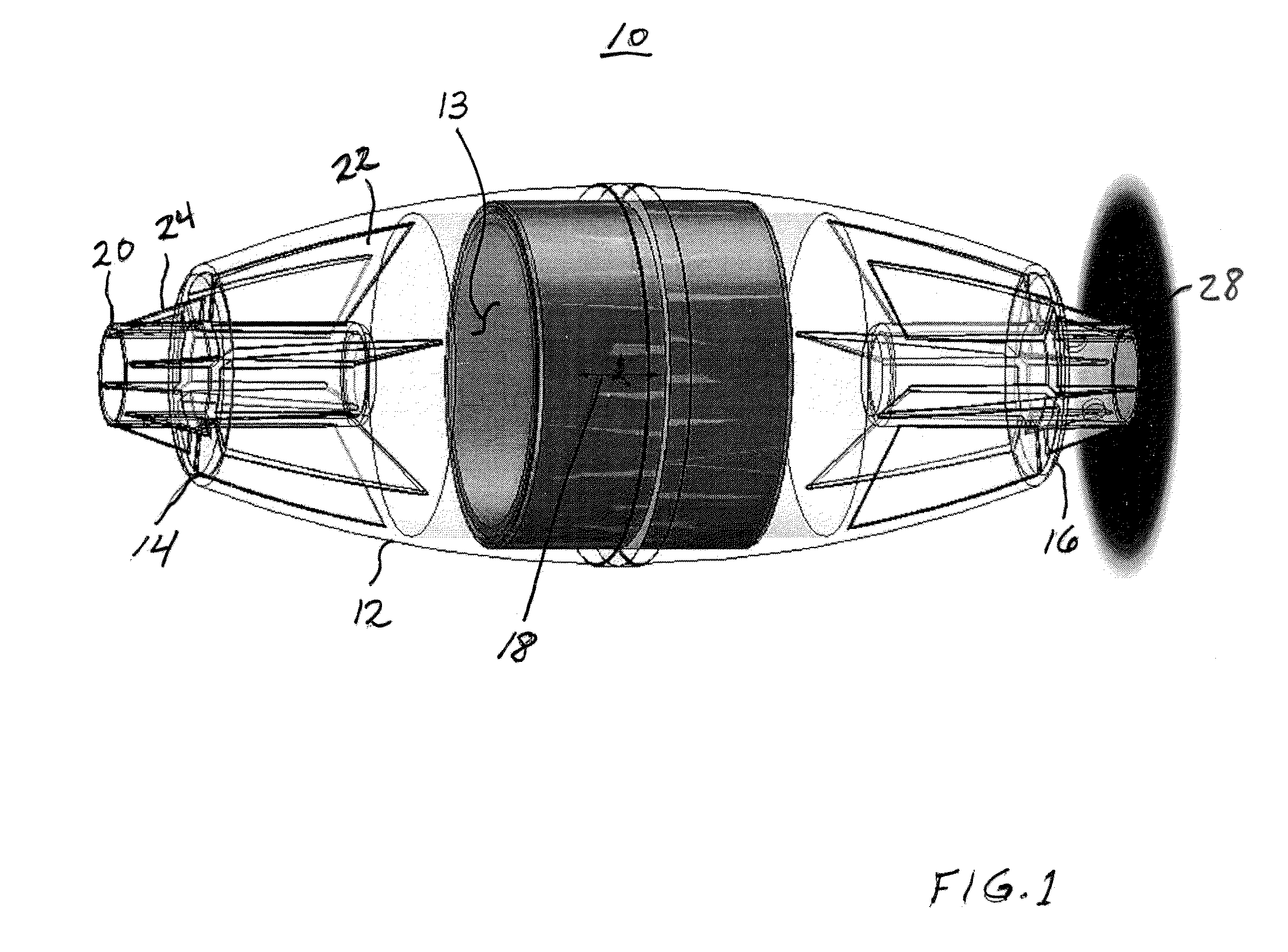
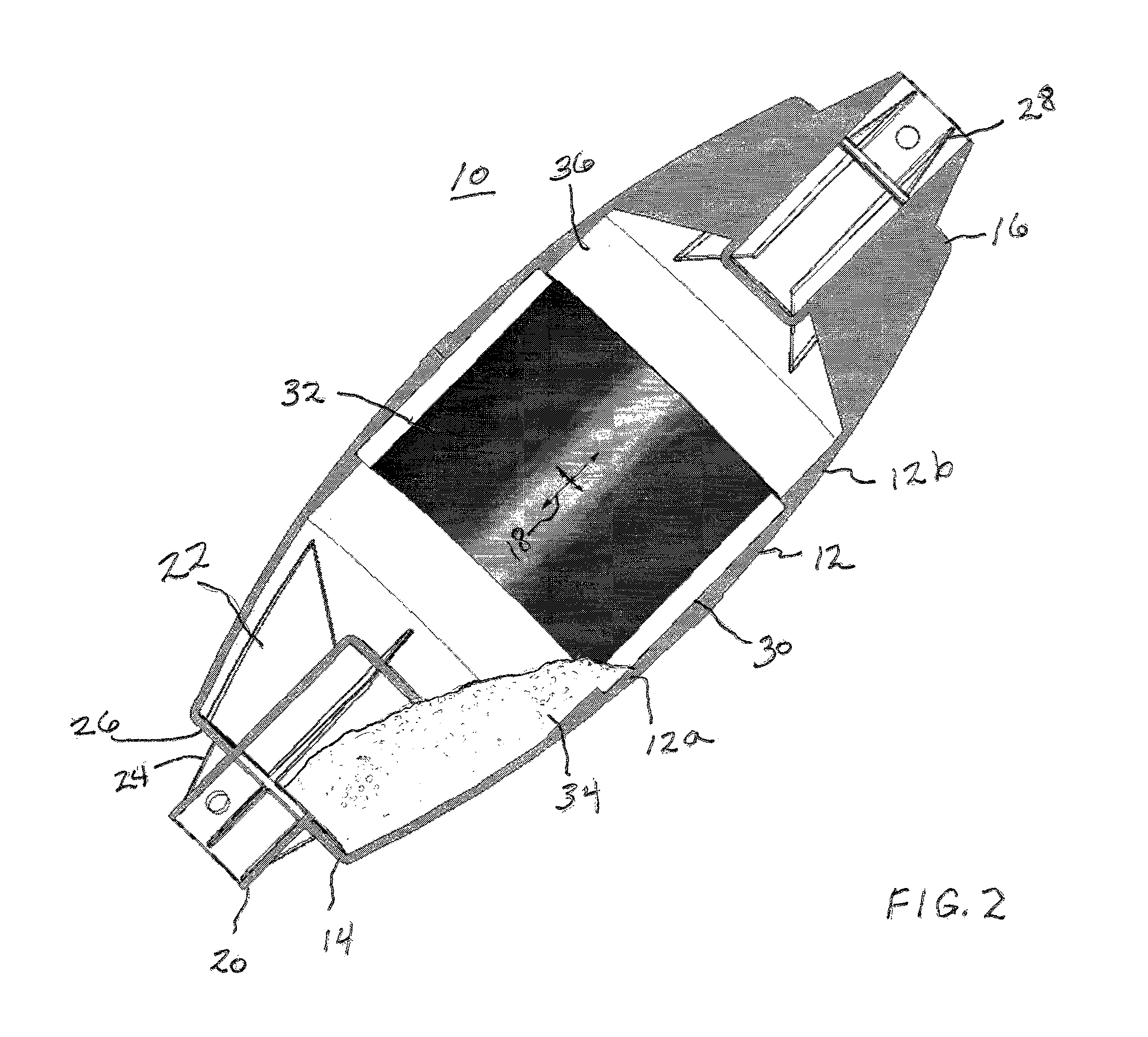
[0015]Turning now to the drawings, attention is first directed to FIGS. 1 and 2 which illustrate an inertial weight 10 in accordance with the present invention. Inertial weight 10 includes a hollow housing 12 defining an inner cavity 13 with first and second spaced apart opposed ends 14 and 16. A longitudinal axis 18 is defined extending therebetween. Inner cavity 13 tapers transversely outwardly along longitudinal axis 18 from a mid section to each of the first and second spaced apart opposed ends 14 and 16. In this preferred embodiment, inertial weight 10 includes housing 12 being generally ellipsoidal shaped with truncated opposed ends 14 and 16. More specifically, longitudinal axis 18 extends from end 14 to the opposed end 16 thereof with the radius of the housing (direction transverse to longitudinal axis 18) gradually tapering or decreasing in length from a midsection toward ends 14 and 16.
[0016]Each end 14 and 16 is provided with an attachment member to allow various elements...
PUM
 Abstract
Description
Claims
Application Information