
Venting mechanisms for battery cells

a battery cell and venting mechanism technology, applied in the field of computer systems, can solve problems such as the risk of burns and other injuries, the inability to meet the requirements of the battery cell, so as to improve the venting effect of the battery cell and prevent the buildup of pressure in the cell

Active Publication Date: 2012-09-11
LENOVO PC INT
View PDF1 Cites 8 Cited by
  • Summary
  • Abstract
  • Description
  • Claims
  • Application Information

AI Technical Summary

Benefits of technology

[0008]Broadly contemplated herein, in accordance with at least one presently preferred embodiment of the present invention, is the provision of improved venting in battery cells by way of better preventing pressure buildup in the cells.
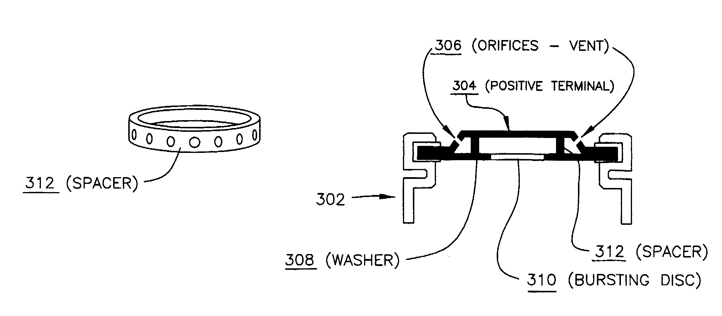
[0010]Furthermore, an additional aspect of the invention provides a battery cell comprising: a terminal; and a venting arrangement which acts to vent gas responsive to pressure buildup within the battery cell; the venting arrangement comprising a yieldable element which yields under pressure and a support which supports the yieldable element; the venting arrangement further comprising windowing disposed in the terminal, the windowing acting to vent gas to ambient; the venting arrangement further comprising a supplementary measure which forestalls collapse of the support and the yieldable element towards the terminal responsive to pressure buildup within the battery cell.

Problems solved by technology

However, increasing demands to package more power into a given cell size are creating a strain on practical and technological limits for some geometries.
The safety hazards from such incidents, although rare, include the potential for causing a fire and the risk of burns and other injury from projectiles and ejected cell contents.
This problem has in fact subjected some battery vendors and equipment manufacturers to a number of well-publicized recalls.
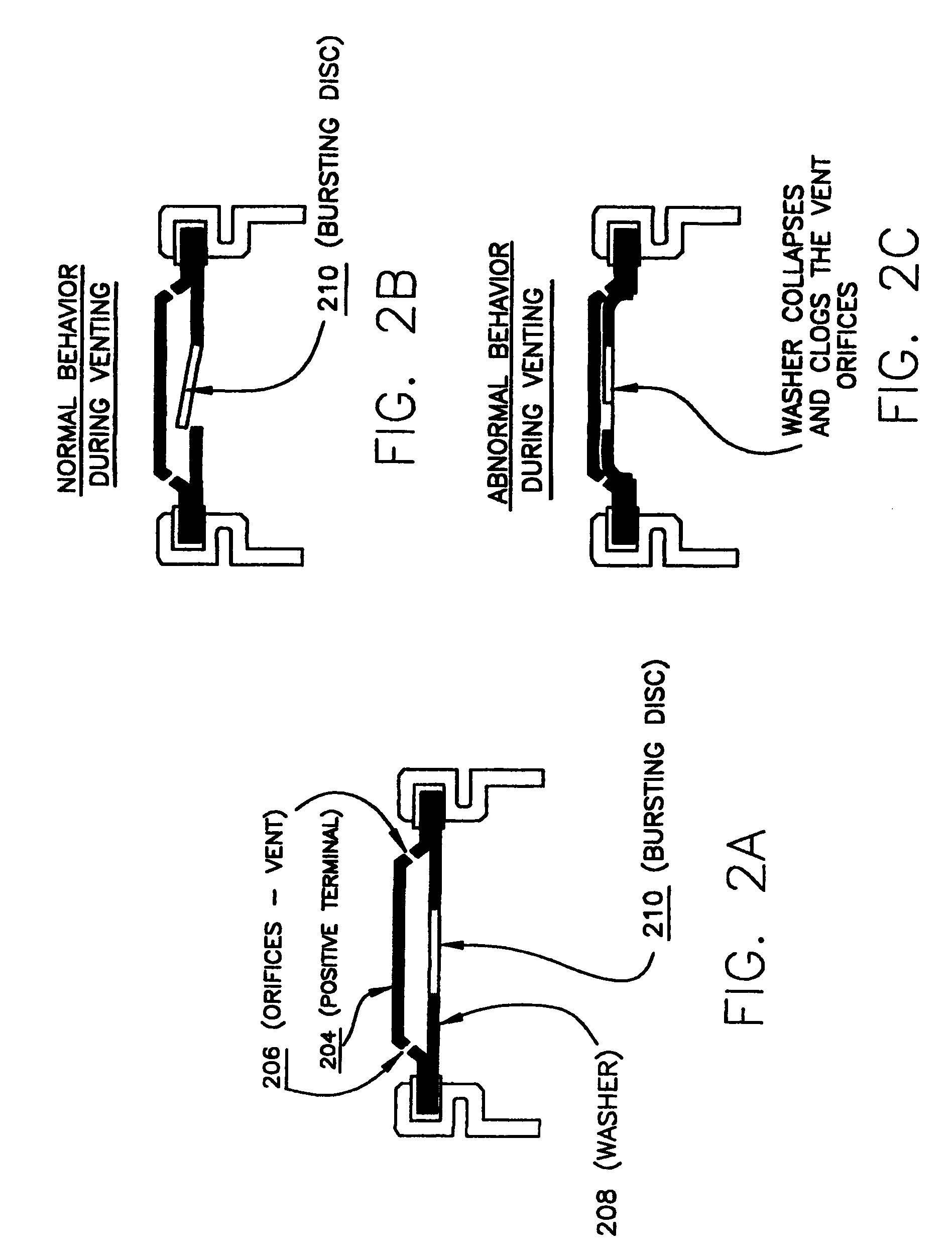
Extensive pinpoint heating tests have shown that some cells are prone to rupture even before thermal runaway (i.e., a rapid increase in temperature), whence a supporting washer collapses and clogs the main venting orifice on the terminal disc (see description of FIG. 2 further below).
While under normal conditions the valve “bursting disc” opens and the gas flows through the opening and exits the cell through terminal orifices, under abnormal conditions the gasket expands and collapses against the terminal and clogs the vent orifices, thereby leading to cell rupture.

Method used


Image

  • Venting mechanisms for battery cells
  • Venting mechanisms for battery cells
  • Venting mechanisms for battery cells

Examples


Embodiment Construction

[0019]For a better understanding of the present invention, together with other and further features and advantages thereof, reference is made to the following description, taken in conjunction with the accompanying drawings, and the scope of the invention will be pointed out in the appended claims.

[0020]It will be readily understood that the components of the present invention, as generally described and illustrated in the Figures herein, may be arranged and designed in a wide variety of different configurations. Thus, the following more detailed description of the embodiments of the apparatus, system, and method of the present invention, as represented in FIGS. 1 through 7, is not intended to limit the scope of the invention, as claimed, but is merely representative of selected embodiments of the invention.

[0021]Reference throughout this specification to “one embodiment” or “an embodiment” (or the like) means that a particular feature, structure, or characteristic described in conn...


PUM

PropertyMeasurementUnit
poweraaaaaaaaaa
pressureaaaaaaaaaa
conductiveaaaaaaaaaa

Abstract

The provision of improved venting in battery cells by way of better preventing pressure buildup in the cells. Via different variants of the present invention, the following advantages are achieved:Gas can escape from the cell without clogging the vent;gas buildup is avoided while the venting valve can operate in a consistently reliable manner;the solutions presented are sufficiently versatile as to be applicable to a variety of cells on the market; andthe risk of explosion is virtually eliminated.

Description

FIELD OF THE INVENTION[0001]The present invention relates generally to computer systems and to methods and arrangements for establishing customer / user defaults in computer systems.BACKGROUND OF THE INVENTION[0002]Rechargeable Lithium-Ion batteries are used extensively in notebook computers, cell phones and many other types of portable equipment primarily because of their relatively low cost and high energy storage capability. However, increasing demands to package more power into a given cell size are creating a strain on practical and technological limits for some geometries. This is evidenced by a marked increase in safety-related incidents where cells have has exploded, ruptured, or vented (i.e., undergone a forced expulsion of gases). The safety hazards from such incidents, although rare, include the potential for causing a fire and the risk of burns and other injury from projectiles and ejected cell contents. This problem has in fact subjected some battery vendors and equipment...

Claims


Application Information

Patent Timeline
Patent Type & Authority Patents(United States)
IPC IPC(8): H01M2/02H01M2/12H01M2/08
CPCH01M2/1229H01M10/42H01M50/325Y02E60/10
Inventor YEBKA, BOUZIANECARLSON, JEREMY R.ESTES, LARRY G.HOLUNG, JOSEPH A.HUMPHREY, TIMOTHYWONG, TIN-LUP
Owner LENOVO PC INT
Learn More