
Passenger ship with outer passageways provided with ventilation means

a technology for passenger ships and passageways, applied in auxilaries, non-magnetic metal hulls, floating buildings, etc., can solve the problems of increasing the price of fossil energy, not providing any added value in terms of pleasantness, and having to reduce the consumption of fossil energy, so as to reduce the energy consumption level of air conditioning used in the passageway, and achieve the effect of reducing the energy consumption level of air conditioning, without affecting the comfort of passengers

Inactive Publication Date: 2012-09-18
STX FRANCE
View PDF12 Cites 0 Cited by
  • Summary
  • Abstract
  • Description
  • Claims
  • Application Information

AI Technical Summary

Benefits of technology

"The present invention proposes a passenger ship that reduces energy consumption for conditioning air without affecting the comfort of passengers. The ship has a superstructure with several decks, with at least one deck containing cabins that have an outer passageway between them. The outer passageway is at least partly closed along its side opposite to the cabins, providing a protected circulation space for the passengers. The air circulation in the outer passageways allows for ventilation without directly blowing conditioned air, providing wellness for the passengers. The outer passageways can be closed or partially closed with transparent or translucent walls, and they can also have means for allowing air to pass through. The floor of the outer passageways can have a grating or a staircase for communication with the outside world. The ship can be a trimaran, and the air-conditioning means can include means for sucking up fresh air."

Problems solved by technology

They therefore form inner circulation areas, which do not provide any added value in terms of pleasantness.
And because of the increase in the price of fossil energies, the navigation sector is itself forced to reduce its consumption of such energies as much as possible.

Method used


Image

  • Passenger ship with outer passageways provided with ventilation means
  • Passenger ship with outer passageways provided with ventilation means
  • Passenger ship with outer passageways provided with ventilation means

Examples


Embodiment Construction

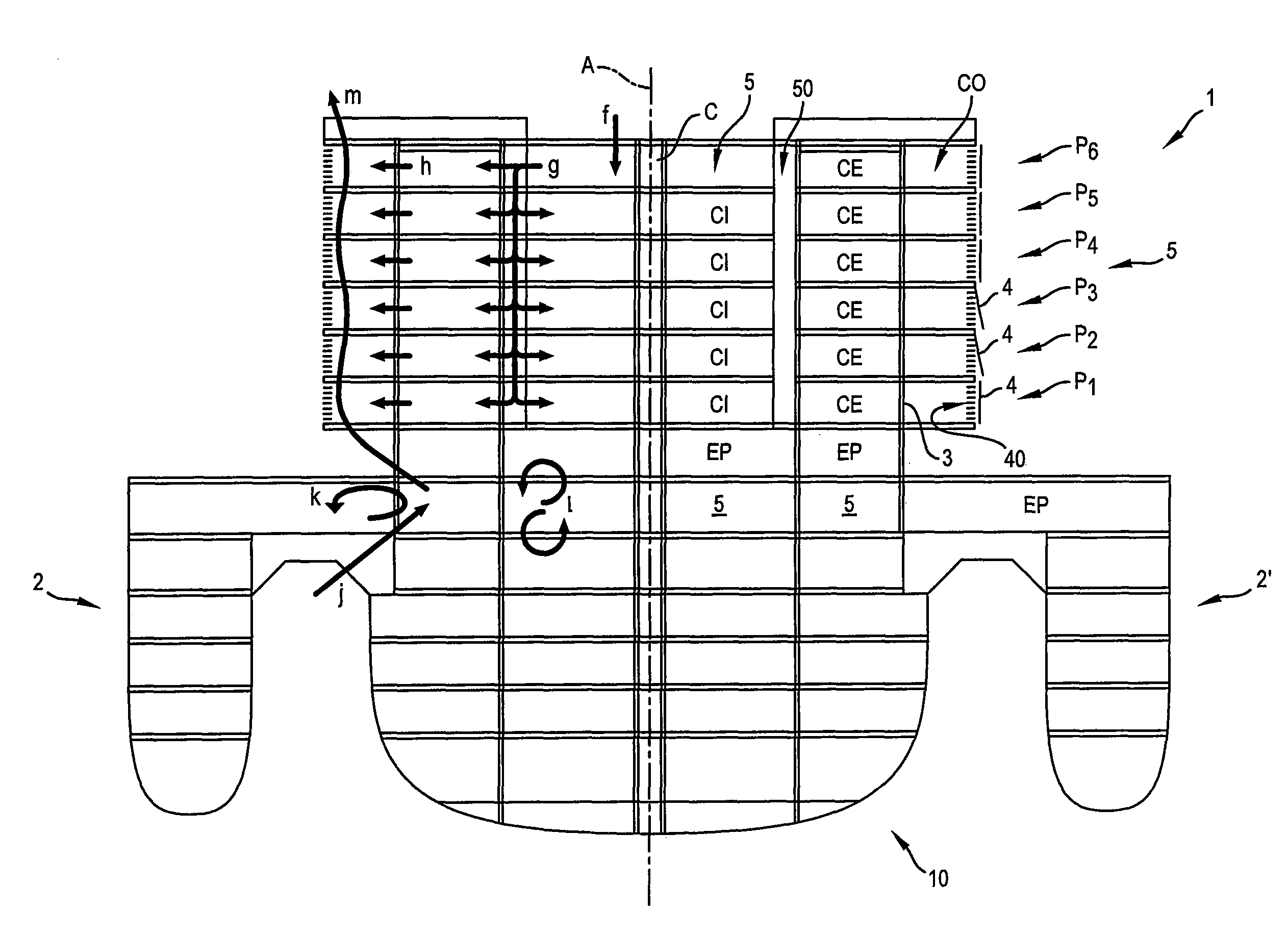
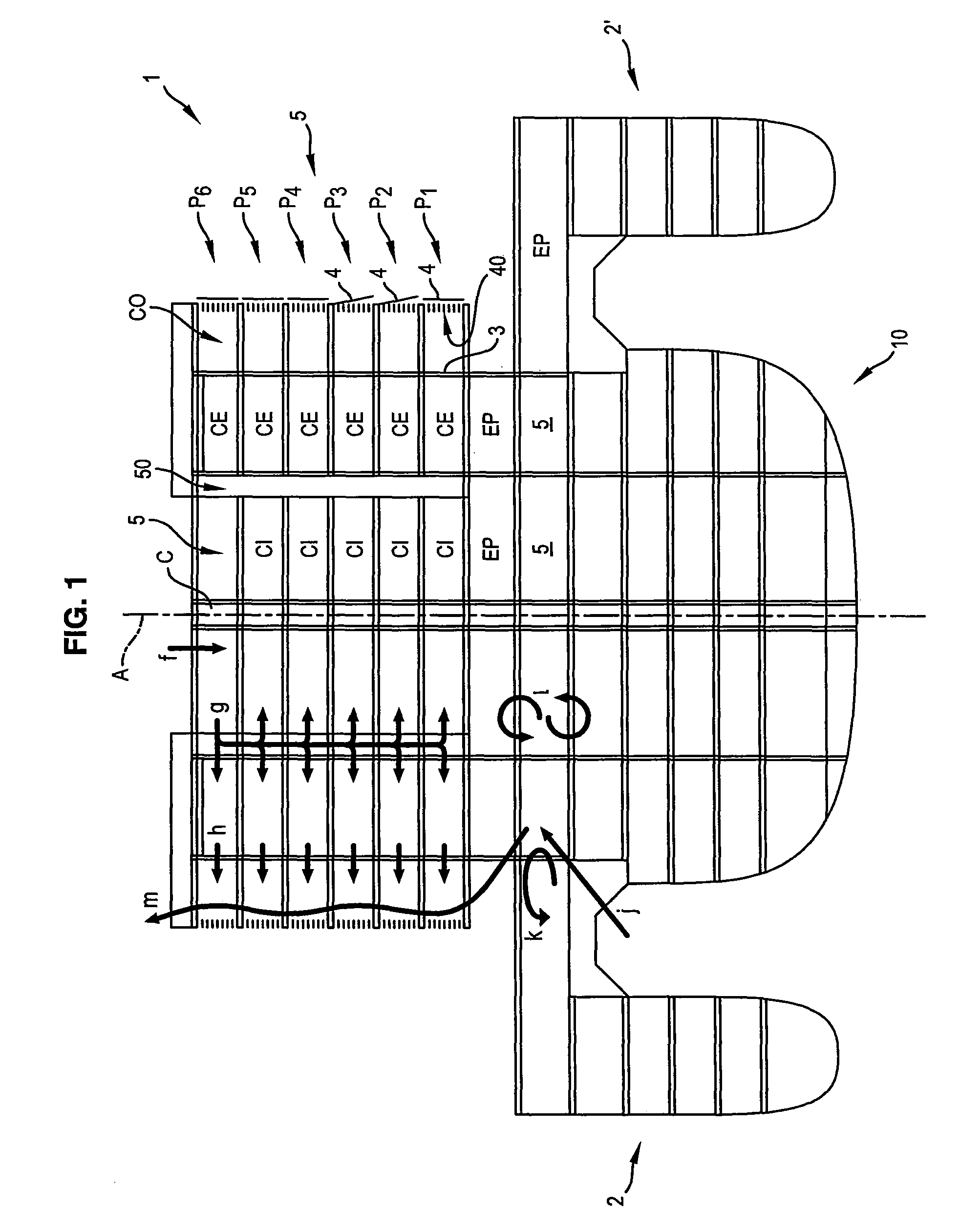
[0035]The ship illustrated in the appended figure is a trimaran. However the present invention applies to any type of passenger ship and most particularly to single-hulled vessels.

[0036]The trimaran 1 illustrated in FIG. 1 includes a central and main hull 10 and two auxiliary hulls 2 and 2′ forming floats. The latter are connected to the main hull through linking arms.

[0037]The longitudinal plane of symmetry of the ship is referenced as A.

[0038]For the sake of the clarity of the figure, only the right portion of the latter bears numerical references, while only the left portion has arrows illustrating the circulating flow of air in the ship.

[0039]However, of course, these numerical references and arrows are both valid for either portion of the ship, because of the perfect symmetry of the latter relatively to the aforementioned plane A.

[0040]The main hull of the ship 1 includes a superstructure S which consists of several superposed decks referenced as P1-P6.

[0041]Of course, in non-i...


PUM


Abstract

A passenger ship includes at least one superstructure having several superposed decks. At least some of the decks include contiguous passenger cabins having an outer longitudinal passageway, which extends between the latter and the hull. Each outer passageway is at least partly closed along its longitudinal side opposite to the cabins. At least one of the opposite ends of each outer passageway is open. The floor which separates outer passageways of two superposed decks is at least partly slatted. The ship includes air-conditioning for the cabins, with discharge of the treated air from the cabins towards the outside world, via said outer passageways. The passenger ship ensures ventilation of the passageways along both longitudinal and vertical directions, respectively, and with the air-conditioning.

Description

BACKGROUND OF THE INVENTION[0001]1. Field of the Invention[0002]The present invention relates to a passenger ship.[0003]2. Discussion of Related Art[0004]Traditionally, such ships include at least one superstructure consisting of several superposed decks, at least one portion of which consists of passenger cabins.[0005]These passenger cabins, whether they are “blind” (i.e. without any view on the sea) or not (which means that they include at least one picture window for having a view on the sea) are accessible from passageways, i.e. long corridors.[0006]These corridors are longitudinally delimited by walls common to the cabins into which they lead. They therefore form inner circulation areas, which do not provide any added value in terms of pleasantness.[0007]These cabins, as well as the associated passageways, are as many public spaces which are traditionally supplied with air-conditioning.[0008]Thus, under winter navigation conditions, they are supplied with heated-up air.[0009]On...

Claims


Application Information

Patent Timeline
Patent Type & Authority Patents(United States)
IPC IPC(8): B63B3/00
CPCB63J2/04B63B29/02
Inventor PELERIN, ERICKTINCELIN, THIBAUT
Owner STX FRANCE
Learn More