Air conditioning system with cold thermal storage and evaporator temperature control

a technology of air conditioning system and evaporator, which is applied in the field of air conditioning system with thermal storage and evaporator temperature control, can solve the problems of inefficient operation of reheating air conditioning system, inability to meet the needs of vehicles, so as to improve vehicle fuel economy, increase the duration of compressor off, and increase the average evaporator air temperature

Inactive Publication Date: 2012-11-06
GM GLOBAL TECH OPERATIONS LLC
View PDF15 Cites 11 Cited by
  • Summary
  • Abstract
  • Description
  • Claims
  • Application Information

AI Technical Summary

Benefits of technology

[0006]An advantage of an embodiment is that a higher average evaporator air temperature (EAT) is achieved without affecting the comfort of vehicle passengers. The higher EAT and cold storage increases compressor off duration, which leads to improved vehicle fuel economy, all while minimizing the long term wear on a compressor clutch by reducing the compressor on-off cycling rates. The extended compressor off time may be particularly advantageous when this air conditioning system is used in a hybrid vehicle. Also, there is improved air conditioning outlet temperature stability during the compressor on-off cycling, again maintaining desired passenger comfort levels.

Problems solved by technology

The use of conventional air conditioning systems in vehicles reduces the fuel economy of the vehicles.
However, for some automotive vehicles, variable capacity compressors may be impractical due to cost or for other reasons.
Operating at maximum cooling of the air with subsequent reheating is an inefficient way to operate the air conditioning system.
But these systems account for only a few variables for air conditioning passenger comfort and so have a fairly limited temperature range that the refrigerant is allowed to fluctuate within.
Thus, maximum fuel efficiency is not obtained.
Moreover, the life of the compressor clutch may be greatly diminished due to a high level of compressor on / off cycling.

Method used


Image

  • Air conditioning system with cold thermal storage and evaporator temperature control
  • Air conditioning system with cold thermal storage and evaporator temperature control
  • Air conditioning system with cold thermal storage and evaporator temperature control

Examples


Embodiment Construction

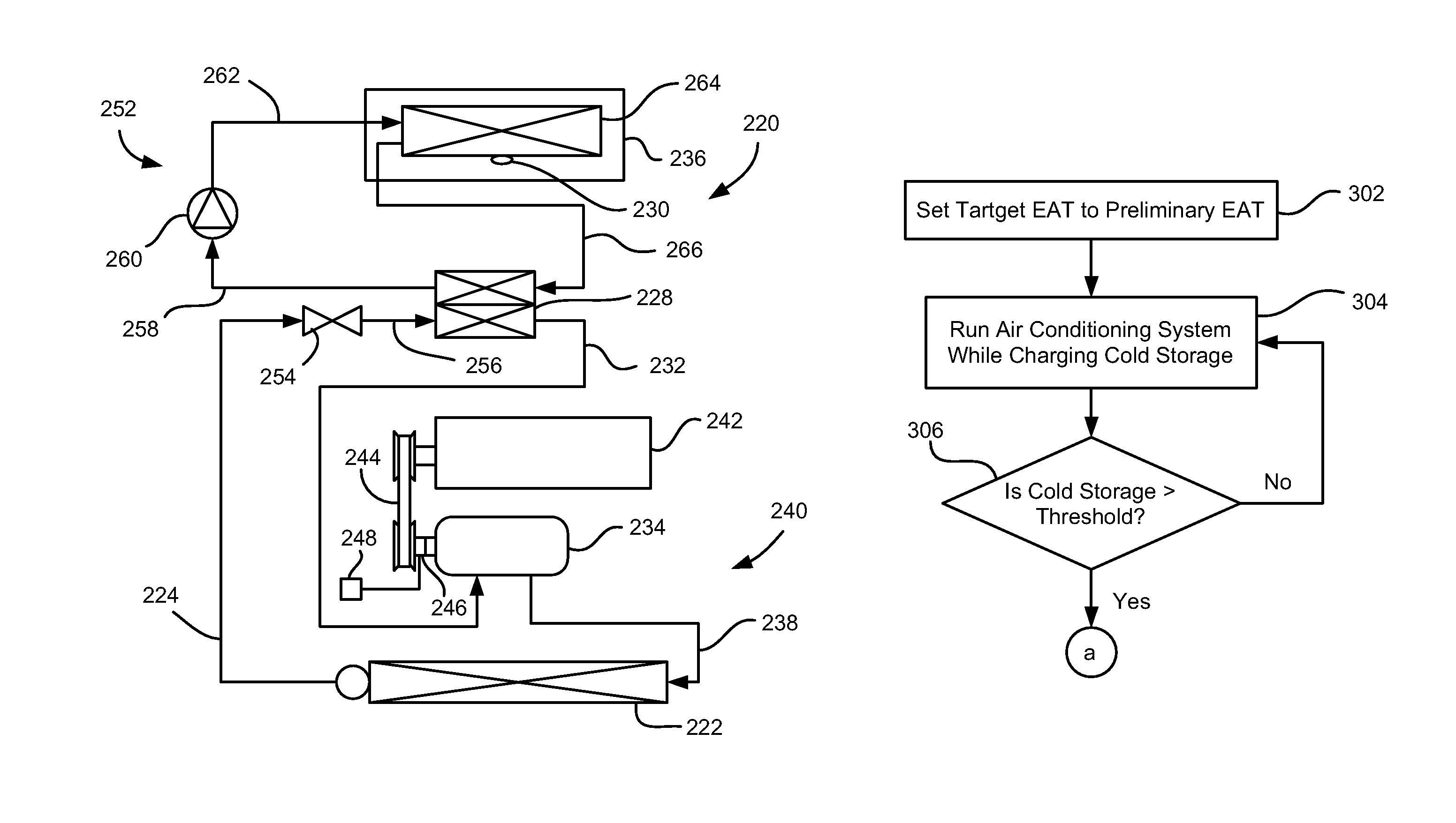
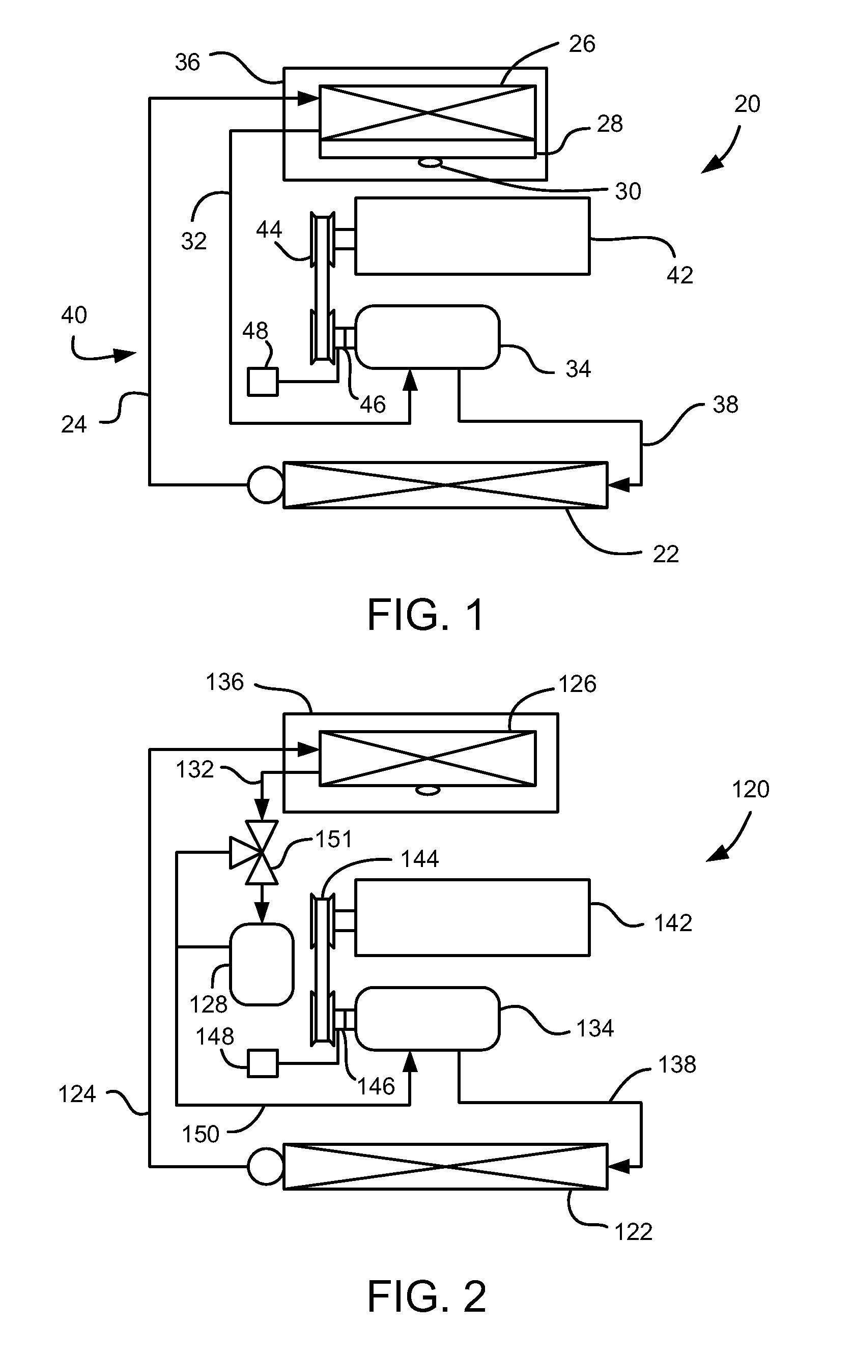
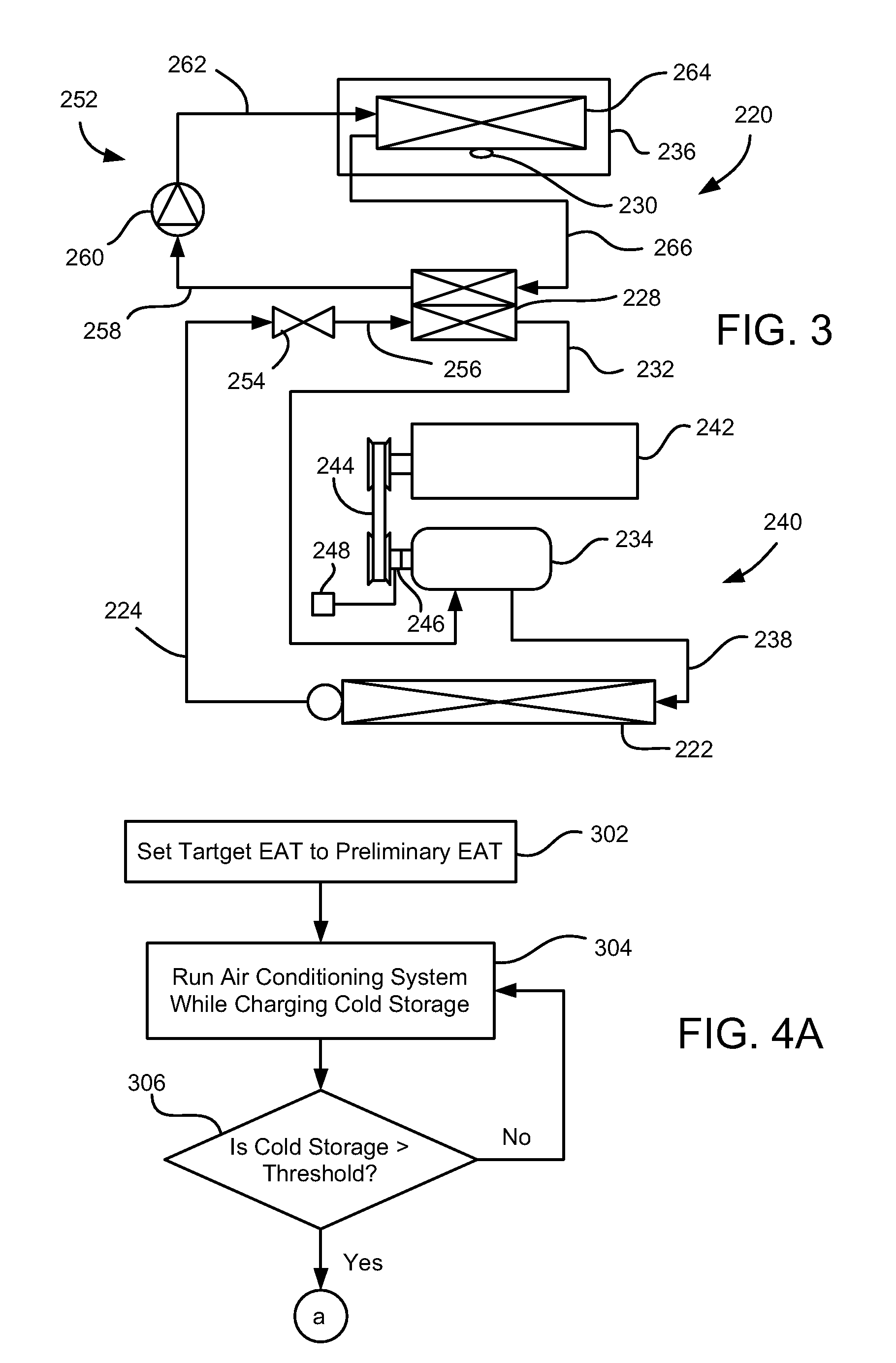
[0011]Referring to FIG. 1, a vehicle air conditioning system 20 is shown. The air conditioning system 20 includes a condenser 22, where heat is drawn from refrigerant before the refrigerant is directed through a refrigerant line 24 into an integrated evaporator and thermal expansion valve assembly 26. This evaporator assembly 26 also includes a cold storage area 28 for the refrigerant. Preferably a phase change material is incorporated in the evaporator assembly 26 to increase specific heat and thermal energy stored in the cold storage area of the evaporator assembly 26. The evaporator assembly 26 is employed to absorb heat from air flowing through a heating, ventilation and air conditioning (HVAC) module 36. A thermistor 30 is located adjacent to the integrated assembly 26 and measures evaporator air temperature (EAT). The thermistor 30 may, for example, measure air temperature adjacent to the evaporator assembly 26 or may measure a temperature on an evaporator fin (not shown). Ano...


PUM


Abstract

A system and method of operating a vehicle air conditioning system having an engine driven, fixed capacity refrigerant compressor and a compressor clutch is disclosed. The method may comprises setting a preliminary evaporator air temperature target; charging a cold storage apparatus in the vehicle air conditioning system; determining if the cold storage apparatus has reached a predetermined threshold; if the cold storage apparatus has reached a predetermined threshold, determining a new evaporator air temperature target by: determining a maximum allowable dewpoint evaporator air temperature for maintaining a passenger compartment humidity below a predetermined value; determining a maximum allowable mode evaporator air temperature based on a mode to which the vehicle air conditioning system is set; and setting the evaporator air temperature target to the lower of the dewpoint evaporator air temperature and the mode evaporator air temperature. The compressor clutch is controlled to achieve the evaporator air temperature target.

Description

BACKGROUND OF INVENTION[0001]The present invention relates generally to air conditioning systems for vehicles, and more particularly to air conditioning systems with thermal storage and evaporator temperature control.[0002]The use of conventional air conditioning systems in vehicles reduces the fuel economy of the vehicles. Given the desire to improve the fuel economy of automotive vehicles, various systems have been employed in an attempt to reduce the fuel economy penalty caused by the air conditioning system. Some air conditioning systems employ variable capacity refrigerant compressors to adjust system capacity to cooling demands and thus improve fuel economy. However, for some automotive vehicles, variable capacity compressors may be impractical due to cost or for other reasons. These other types of air conditioning systems typically employ a fixed capacity compressor that is driven by the engine, with a compressor clutch cycled on and off to switch between full compressor capa...

Claims


Application Information

Patent Timeline
Patent Type & Authority Patents(United States)
IPC IPC(8): B60H1/32F25B1/00B60H1/00F24F6/00
CPCB60H1/005B60H1/00735B60H1/3207B60H2001/3261B60H2001/327B60H1/32281
Inventor MAJOR, GREGORY A.FREY, JOHN I.PORRETT, KENNETH L.
Owner GM GLOBAL TECH OPERATIONS LLC
Why Eureka
Try Eureka