Railway brake shoe

a brake shoe and rail technology, applied in the direction of brake elements, brake members, friction linings, etc., can solve the problems of difficult or inability to obtain the benefits of metal inserts

Active Publication Date: 2012-09-18
RFPC HLDG CORP
View PDF58 Cites 5 Cited by
  • Summary
  • Abstract
  • Description
  • Claims
  • Application Information

AI Technical Summary

Benefits of technology

[0007]It is an advantage of this invention to provide a metal insert uniquely configured for use in brake shoes without metal backing plates and brakes shoes incorporating the metal insert. It is an additional advantage of this invention to provide metal inserts that may be used with brake shoes with and without wire frame supports.
[0010]According to a further embodiment, a bridge is provided across the radial ends of the parallel flanges of the insert to provide a closed keyway. According to yet another embodiment, the spaced bodies and the connection portion have openings therethrough for the passage of friction material. Thus, the friction material is not completely interrupted by the insert positioned between both circumferential (longitudinal) ends of the brake shoe thereby holding both ends together.

Problems solved by technology

As a result, it is difficult or not possible to obtain the benefits of a metal insert due to the lack of an adequate means for support and retention of the metal insert.

Method used


Image

  • Railway brake shoe
  • Railway brake shoe
  • Railway brake shoe

Examples


Embodiment Construction

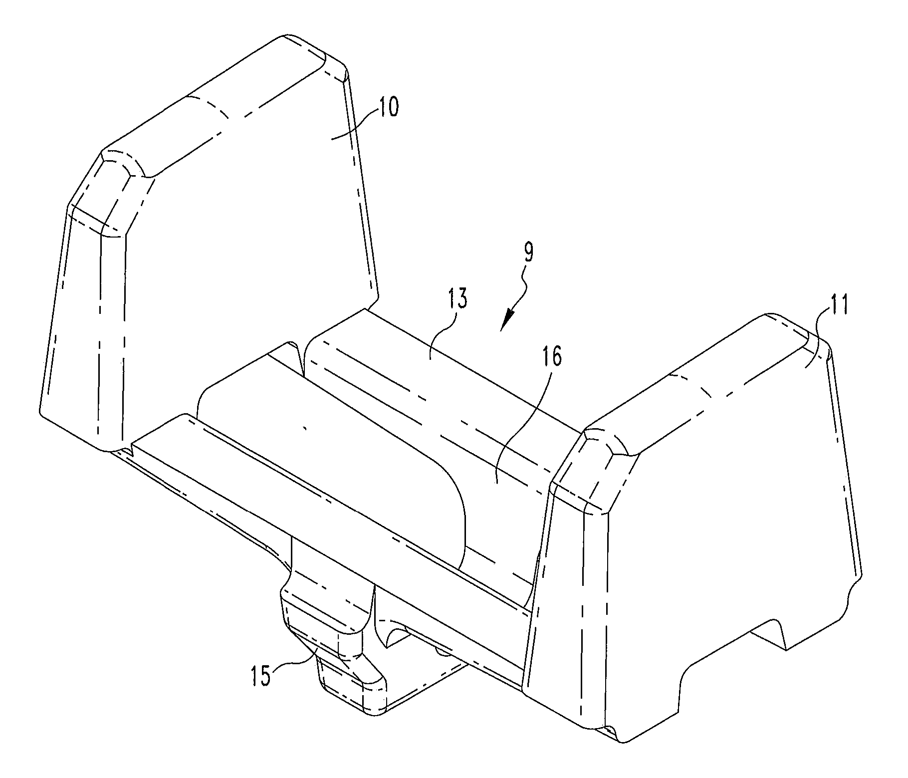
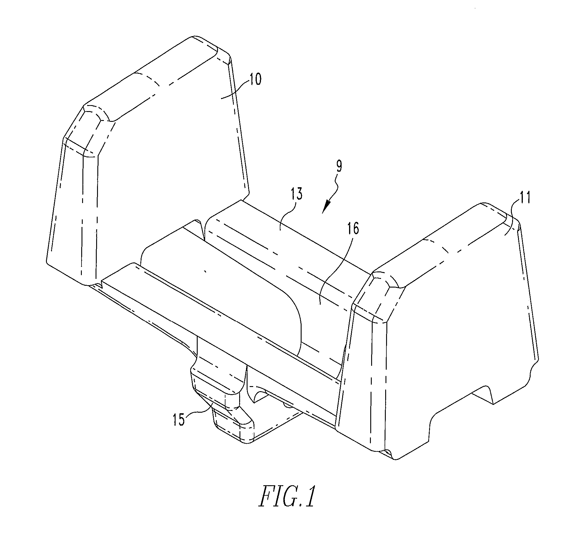
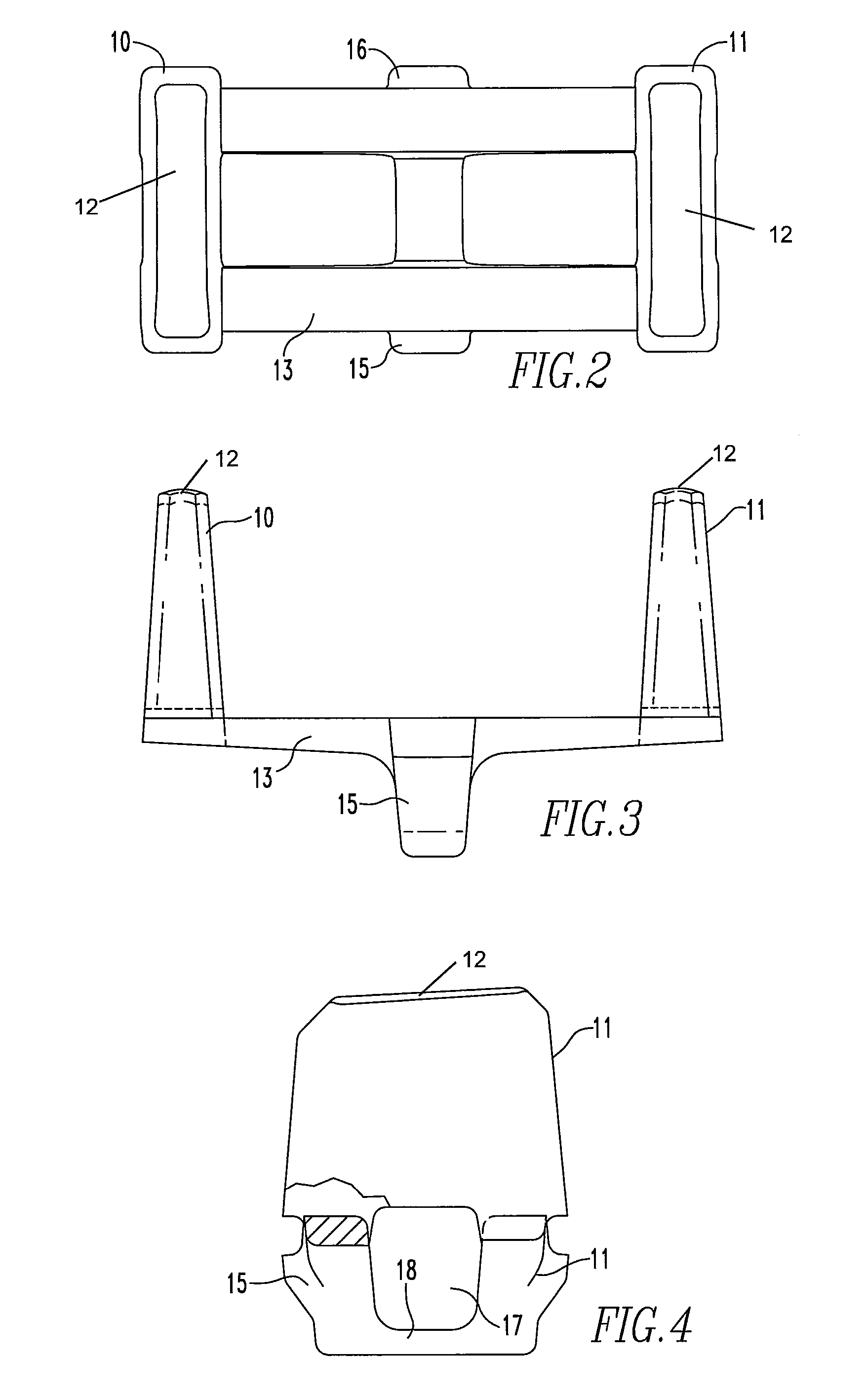
[0021]Referring now to FIGS. 1 to 4, there is shown an insert for a brake shoe without a metal backing. A brake shoe is defined by a friction surface for bearing upon a wheel tread and an opposed back surface for being placed in contact with and secured to a brake head. A metal insert 9 comprises two spaced apart bodies 10, 11 having friction faces 12 for lying in the friction surface of a brake shoe. The two spaced apart bodies 10, 11 extend away from the friction face 12.

[0022]A connecting portion 13 extends between the two spaced bodies. The connecting portion has a back face for being positioned adjacent to the back surface of the brake shoe and providing brake head support. Two generally parallel radially extending flanges 15, 16 are integral with the connecting portion 13. The parallel flanges 15, 16 are sized for extending beyond the back surface of a brake shoe thus defining a keyway 17. As shown in FIG. 4 a bridge 18 extends between parallel flanges 15, 16 to enclose the ke...


PUM


Abstract

A brake shoe without a metal backing has a metal insert comprising two spaced apart bodies, a connecting portion having a back face adjacent to the back surface of the brake shoe, and two generally parallel radially extending flanges integral with the connecting portion. The parallel extensions define a keyway, wherein when the brake shoe is emplaced on the brake head, the keyway extends through an opening provided in the brake head.

Description

BACKGROUND OF THE INVENTION[0001]1. Field of the Invention[0002]This application is directed to the art of composite railway brake shoes.[0003]2. Description of Related Art[0004]Rail cars are supported and guided by steel wheels. The treads at the outer circumference of the wheels ride over steel rails. Rail car brakes comprise brake shoes that are brought into frictional engagement with the wheel treads. The brake shoes are supported by brake heads which, in turn, are movably supported by the brake rigging comprised of a system of levers and a pneumatic cylinder. Brake shoes are comprised of various materials that are selected for their frictional characteristics and for the effect on the wear life of the wheel treads. Many brake shoes are composites of materials having different characteristics. In typical composite brakes shoes, materials of differing frictional characteristics bear upon the wheel tread during braking. This may be achieved by placing inserts of a different materi...

Claims


Application Information

Patent Timeline
Patent Type & Authority Patents(United States)
IPC IPC(8): F16D65/04F16D69/00
CPCF16D65/0037F16D65/062F16D2069/002
Inventor KAHR, JOSEPH C.RUMPH, TIMOTHY A.
Owner RFPC HLDG CORP
Why Eureka
Try Eureka