High strength hook, in particular for elastic cable

a high-strength, elastic cable technology, applied in the field of hooks, can solve problems such as insufficient retention

Inactive Publication Date: 2005-09-06
JOUBERT SA
View PDF30 Cites 27 Cited by
  • Summary
  • Abstract
  • Description
  • Claims
  • Application Information

AI Technical Summary

Problems solved by technology

When very high levels of traction are app

Method used


Image

  • High strength hook, in particular for elastic cable
  • High strength hook, in particular for elastic cable
  • High strength hook, in particular for elastic cable

Examples


Embodiment Construction

[0016]In each case, the scale of the figures is appropriate for the corresponding explanations.

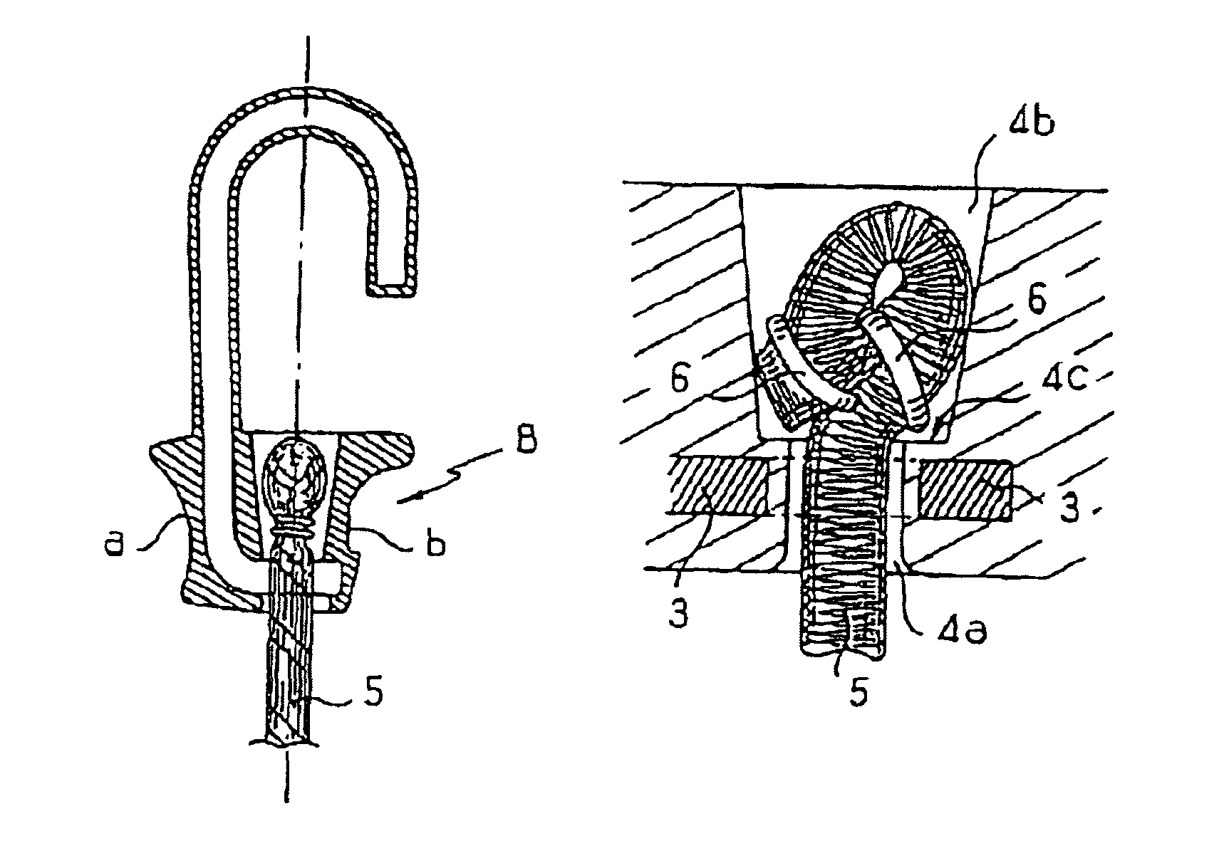
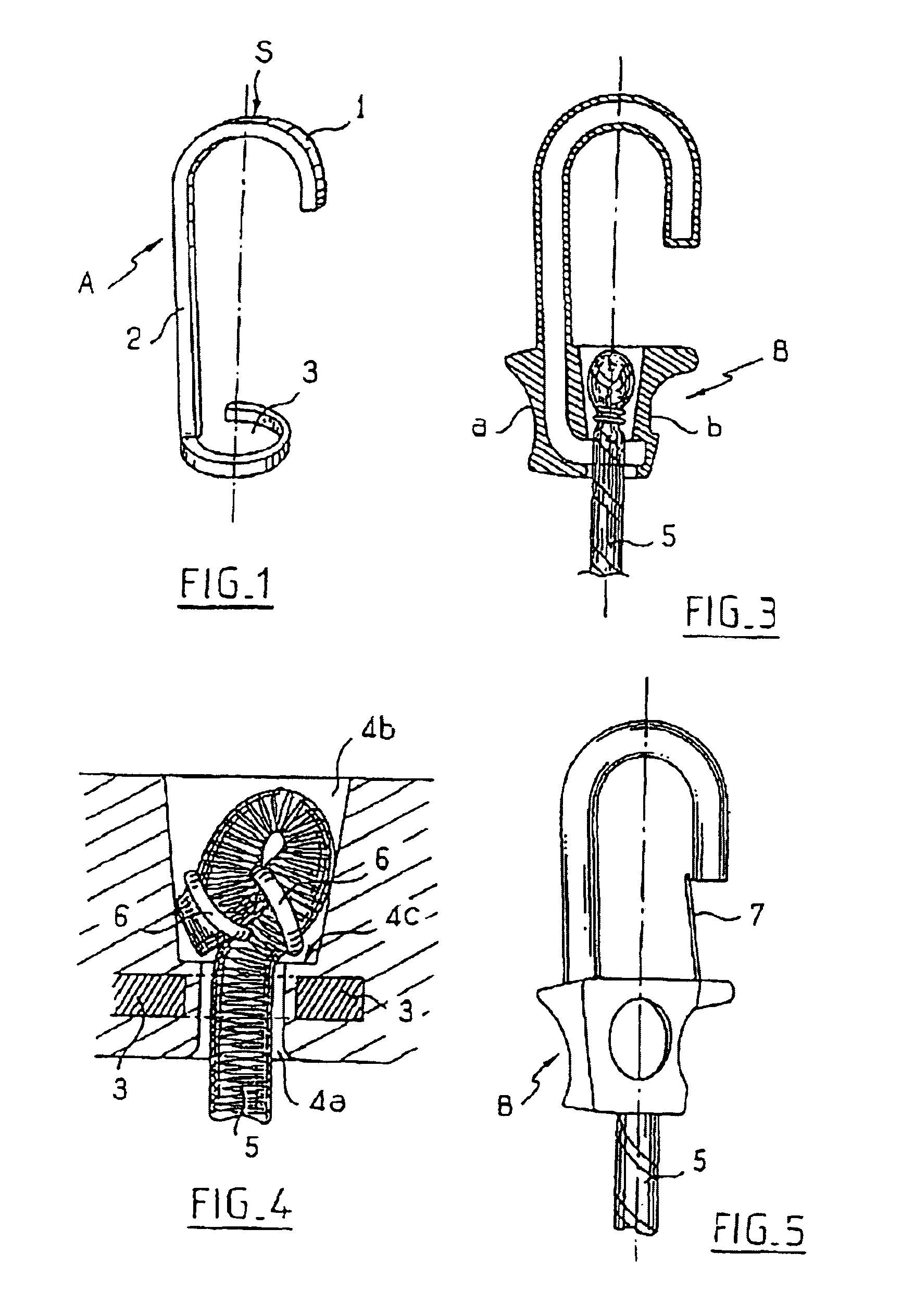
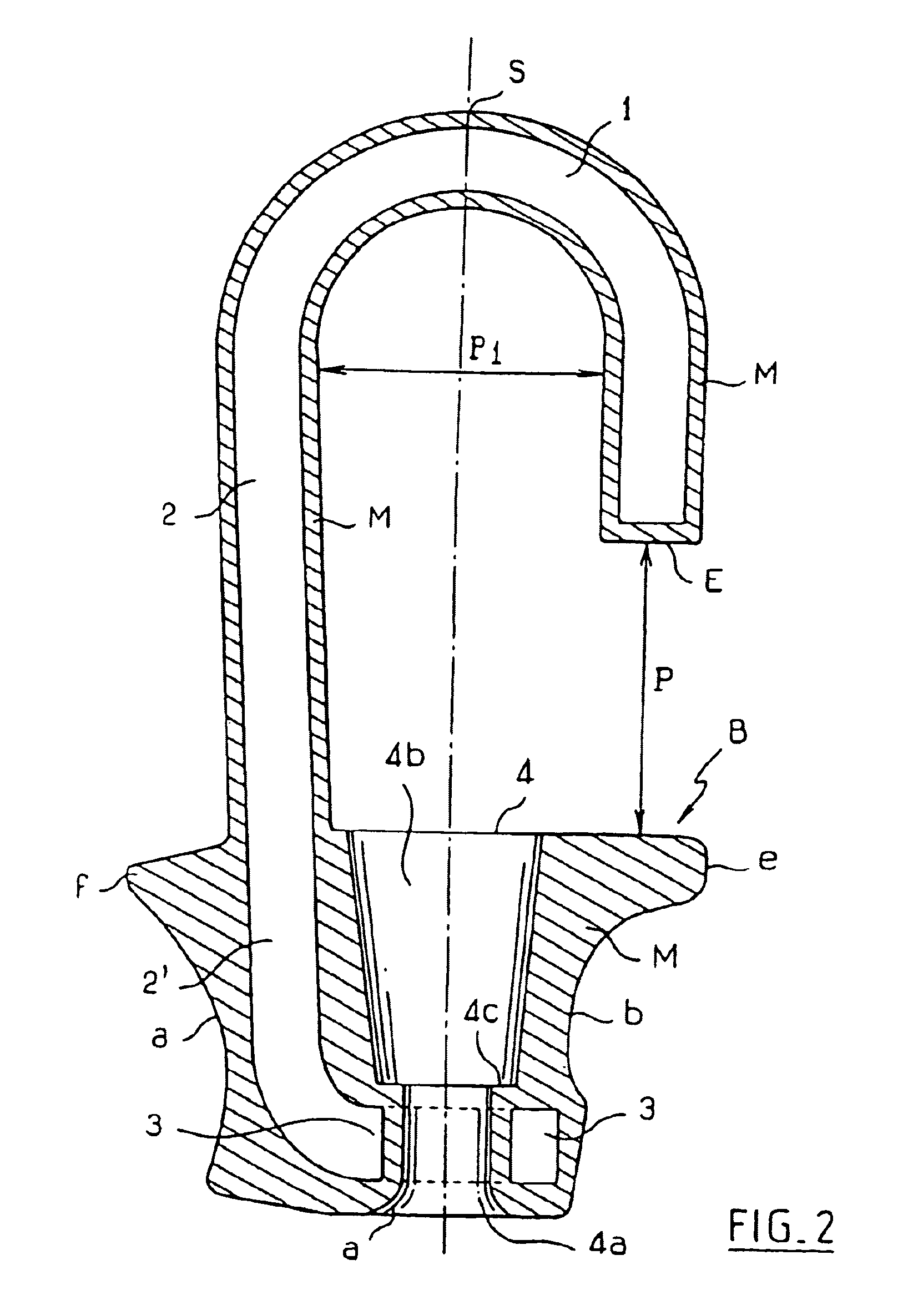
[0017]The reinforcement (A) of the hook is constituted (see FIG. 1) by a rigid metal wire (A) having one end (1) curved into an upside-down J-shape and having its other end bent so as to lie in a plane perpendicular to the plane of the J-shape and curved so as to form an open or closed ring (3) therein.

[0018]The hook is preferably made of steel flat with an optionally rounded edge, the hook being formed edgewise so as to provide the greatest possible strength.

[0019]The ring (3) is substantially on the same axis as the top (S) of the curve of the J-shape and the shank (2) of the J-shape slopes slightly outwards going away from the ring.

[0020]This wire is placed in the cavity of an injection mold so as to be coated in a synthetic resin or some other suitable material. For this operation, it is possible for example to use polyethylene or polypropylene for conventional hooks, or a polyamide or...


PUM


Abstract

The invention relates to a high strength hook. The hook comprises an annular metal insert (3) embedded in a synthetic material end block of the hook around a passage (4) for slidably receiving the end of a cable (5) in the vicinity of a stop abutment (4c) designed to stop the end of the cable in the traction direction. The invention is applicable to hooks comprising a metal hook having an end embedded in a handle block.

Description

FIELD OF THE INVENTION[0001]The present invention relates to a hook of the type having, at one end, a handle block of synthetic material shaped to facilitate taking hold of the hook and having a passage passing therethrough for receiving and retaining in the block a cable to which the hook is to be fixed.BACKGROUND OF THE INVENTION[0002]Such a hook is described in publication U.S. Pat. No. 5,317,788, for example.[0003]To retain the cable in the hook when traction is applied to the cable tending to extract it from the hook, the passage tapers so as to define an abutment for stopping the end of the cable once said end has been enlarged after being passed through the passage. In the embodiment described in the above-specified publication, the end of the cable is enlarged by folding the end back onto the cable and by holding the end in place in a metal ring, and the passage through the block is designed so as to receive the enlarged end of the cable when traction is applied to the cable...

Claims


Application Information

Patent Timeline
IPC IPC(8): F16B45/00F16B45/02
CPCF16B45/00Y10T24/4755Y10T24/314F16B45/012F16B45/008
Inventor JOUBERT, XAVIERJOUBERT, THIERRY
Owner JOUBERT SA
Why Eureka
Try Eureka