Implantable sling for the treatment of incontinence and method of using the same

a technology of incontinence and implants, which is applied in the field of surgical implants for the treatment of male or female incontinence, can solve the problems of incontinence experiencing continuous urine leakage, incontinence changing, and urge incontinence, and achieves the effects of convenient anchoring, less trauma, and less urination

Active Publication Date: 2009-07-14
COLOPLAST AS
View PDF6 Cites 75 Cited by
  • Summary
  • Abstract
  • Description
  • Claims
  • Application Information

AI Technical Summary

Benefits of technology

[0011]The present invention specifically addresses and alleviates the above-identified deficiencies in the art. In this regard, the present invention is directed to suburethral sling implants and methods of deploying the same that are effective and substantially easier to deploy than prior art implants and implantation techniques for treating incontinence. The implant comprises the combination of a urethral support portion and at least one anchoring portion. The support portion is operatively positioned at or distal to the bulbar urethra (male) or mid-urethral region (female). Per conventional suburethral slings, the support portion is operative to provide structural support to the urethra such that during the occurrence of a provocative event, the sling is operative to compressively engage the urethra to prevent urine leaking therefrom. The support portion will have a surface area that is at least 2 cm long by 1 cm wide to 8 cm long by 8 cm wide. Along these lines, it should be understood that the specific dimensions provided herein can vary by 50% or substantially greater, and retain its ability for use as an implant.
[0014]Regardless of the embodiment, in all procedures involving the implantation of the implants of the present invention, such procedures are performed with the patient assuming a lithotomy position. A vertical perineal (male) or vaginal (female) incision is made in the midline dissecting to expose the bulbar urethra (male) or urethra (female) and the inferior aspect of the descending rami bilaterally. A surgical introducer is utilized to introduce the implant into position, typically through the obturator foramen, in a manner that is substantially easier and less traumatic than conventional surgical procedures utilized to access and implant slings for the treatment of male or female incontinence. Once the surgical site is accessed, the anchoring portion will preferably be positioned through the obturator foramen and anchored into position. Surgical sutures and the like may be deployed to facilitate anchoring of the anchor portions of the implant. Minor variations well-known to those skilled in the art may necessarily be made to effectuate optimal attachment and positioning of the support portion of the implant, as may be necessary for a given patient. In all cases, however, the surgical procedures and implants of the present invention provide a radically more efficient, effective and less traumatic surgical approach to the treatment of male or female incontinence.

Problems solved by technology

In addition, it is known that urinary incontinence may change over time and that men and women with light incontinence, for example, may experience minimal leakage during the occurrence of a provocative event, such as laughing or coughing, whereas men and women with heavy incontinence may experience continuous urine leakage.
Urge incontinence occurs when the patient wants to urinate but is incapable of exercising restraint until reaching a restroom.
Additional types of incontinence include. overflow incontinence, which occurs when the quantity of urine exceeds the capacity of the patient's bladder, and functional incontinence, which occurs when the patient has knowledge of the need to urinate but simply cannot access a restroom quickly enough due to a physical obstruction or debilitation.
Utilizing sling implants to treat incontinence, however, has been known to have numerous drawbacks.
Securing suburethral sling implants into position typically requires the use of bone screws, which are well-known in the art to be difficult and time consuming to deploy, and can result in significant patient discomfort, especially within the first couple of weeks following the surgical implantation.
In addition, implanting suburethral slings are often times difficult to secure into position with the optimal degree of tension.
Indeed, the implantation of suburethral slings for the treatment of incontinence is well-recognized as complex, time consuming and can produce suboptimal clinical outcomes.
Moreover, it is well recognized among surgeons that perform such implant procedures that sutures attached to bone anchors and / or sutures attached to bone screws utilized to secure the sling into position frequently break and that often times additional bone anchors or screws must be secured into position.

Method used


Image

  • Implantable sling for the treatment of incontinence and method of using the same
  • Implantable sling for the treatment of incontinence and method of using the same
  • Implantable sling for the treatment of incontinence and method of using the same

Examples


embodiment 400

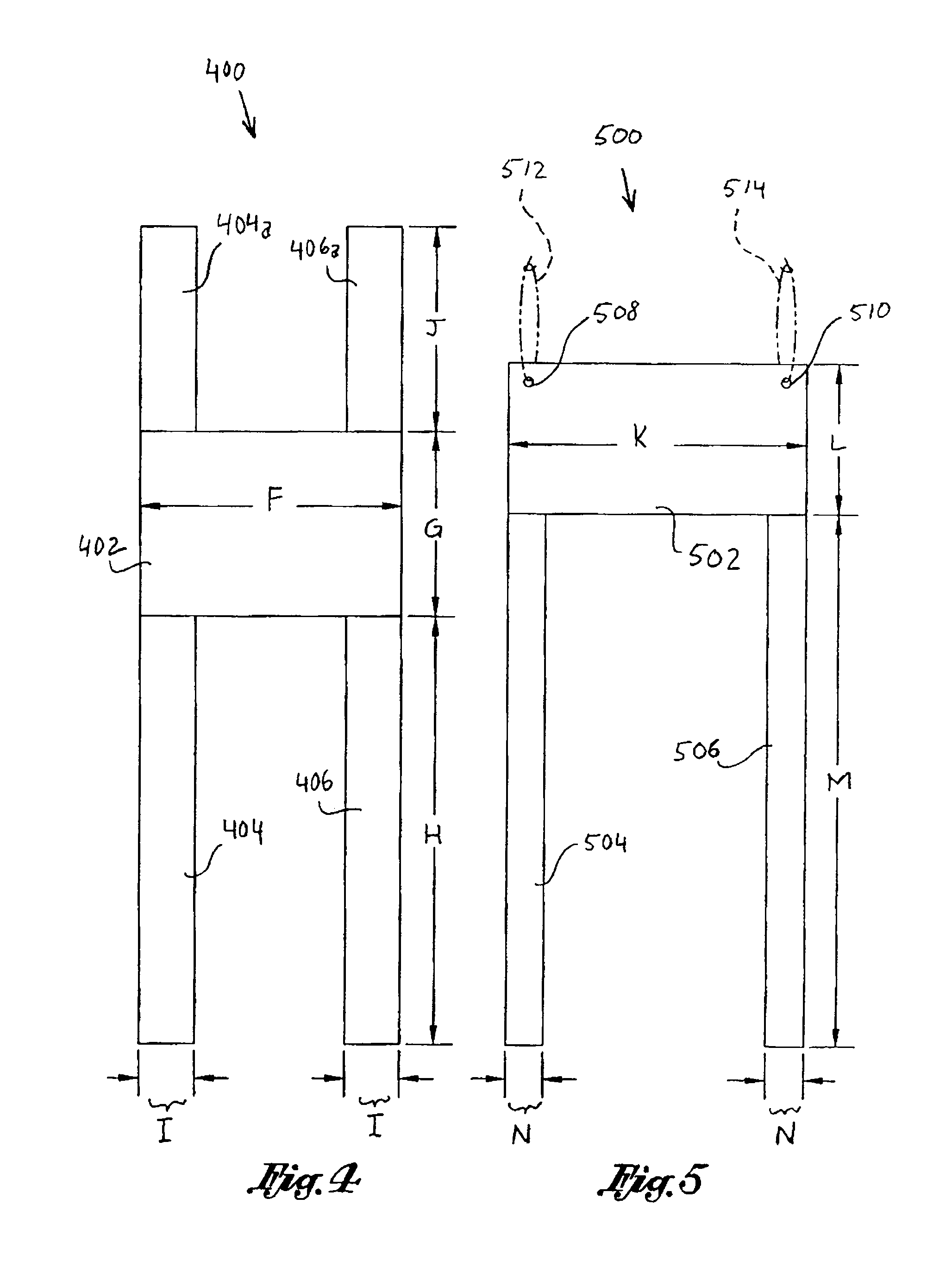
[0044]Referring now to FIG. 4, there is shown a further embodiment 400 for use in the surgical treatment of male urinary incontinence. As depicted, the implant 400 includes a support portion 402 with first and second anchor portions 404, 406 depending therefrom in generally parallel relation to one another and additional anchor portions 404a, 406a, ascending therefrom to define an “H” shape. The implant 400, as depicted, is preferably formed such that support portion 402 has a width “F” of approximately 7 cm and a height “G” of approximately 5 cm. Anchor portions 404, 406 preferably have a length “H” of approximately 30 cm and a width “I” of 1 cm. Additional anchor portions 404a, 406a will have a width of approximately 1.5 cm and a height “J” of approximately 14 cm, and may preferably be formed as extensions of 404 and 406, respectively. Again, such dimensions can be varied as may be deemed appropriate by one skilled in the art. Specifically, it should be understood that the specifi...

embodiment 600

[0056]To implant such embodiment 600, a vertical perineal incision is made in the midline dissecting to expose the bulbar urethra and the inferior aspect of the descending rami bilaterally while the patient assumes a lithotomy position. A suitable introducer is passed from outside in or inside out through a 3 cm groin incision that is chosen with the finger in the initial perineal incision to pass through the obturator foramen. A respective end 604 or 606 that is attached to the introducer tip and advanced within the perineal incision. The introducer is retracted through the obturator foramen with the respective other end 604 or 606 being grasped at the lateral groin incision site and cut at skin level. The opposite end 604 or 606 is carried over the bulbar urethral complex. A second suitable introducer is passed from outside in or inside out through another 3 cm groin incision on the contra-lateral side and the process is repeated. The respective ends 604 and 606 of the implant 600...

embodiment 700

[0057]The implant in embodiment 700 depicted in FIG. 7 assumes a generally rectangular configuration having a width “Q” of 4 cm and a height “R” of 3 cm. In accordance with the other embodiments, the implant is preferably secured into position by making a vertical perineal incision to the midline dissecting to expose the bulbar urethra and the inferior aspect of the descending rami bilaterally while the patient assumes a lithotomy position. A suture secured on a UR-6 needle is then used to bite into the periosteum of the descending rami bilaterally. Although not shown, there will be four sutures altogether on each side for a total of 8 secured knots to fix the implant 700 into position. The lower three sutures on one side are threaded through the implant, which is placed as high as possible on the bulbar urethral complex. Such lower three sutures are loosely held to stabilize the sling and the top apical suture is then placed, one on each side at the junction of the descending rami ...


PUM


Abstract

An implantable sling for the treatment of male or female incontinence and method of implementing the same. The sling comprises a urethral support portion and at least one anchoring portion extending therefrom. The anchoring portion is operatively positioned through the obturator foramen and about at least one ramus portion of the pelvis such that the support portion of the implant is operatively positioned at or distal to the bulbar urethra (male) or mid-urethral region (female) to treat urinary incontinence. In a preferred embodiment, the implant will have first and second anchoring portions extending from the support portion with each respective one of said anchoring portions being operative to be secured about dedicated ones of the patient's pubic ramus. The implants may further be fabricated from tissues, synthetic materials or combinations thereof.

Description

CROSS-REFERENCE TO RELATED APPLICATIONS[0001]The present application claims benefit of U.S. Provisional Application Ser. No. 60 / 773,565 filed Feb. 14, 2006, which is hereby incorporated by reference.BACKGROUND OF THE INVENTION[0002]The present invention is directed to surgical implants for the treatment of male or female incontinence, and in particular, implantable slings that are operative to provide sling-type support at or distal to the bulbar urethral region (male) or mid-urethral region (female) of a patient and operatively anchored into position via fixation about the patient's descending rami.[0003]Of the estimated 19 million North American adults who have urinary incontinence, 20% are estimated to be men. Such condition can range in severity from partial to complete loss of bladder control and patients afflicted with urinary incontinence can experience varying degrees of urine loss. In addition, it is known that urinary incontinence may change over time and that men and wome...

Claims


Application Information

Patent Timeline
Patent Type & Authority Patents(United States)
IPC IPC(8): A61F2/02
CPCA61B17/06109A61F2/0045A61B2017/06076A61B2017/00805A61F2220/0008A61F2230/0013A61F2230/0039A61F2230/0058
Inventor MERADE, BRYON L.COMITER, CRAIGNITTI, VICTORRACKLEY, RAYMONDRHEE, EUGENEVASAVADA, SANDIPELLENSON, KAPRI
Owner COLOPLAST AS
Why Eureka
Try Eureka