Inflatable annular sealing device for prosthetic mitral valve

a prosthetic heart valve and annular sealing technology, applied in the field of improved transcatheter prosthetic heart valves, can solve the problems of high morbidity, high risk of open heart surgery, and high risk of mortality, and achieve the effect of reducing or preventing leakag

Active Publication Date: 2016-11-08
TENDYNE HLDG
View PDF691 Cites 71 Cited by
  • Summary
  • Abstract
  • Description
  • Claims
  • Application Information

AI Technical Summary

Benefits of technology

[0014]The present invention relates to the improved design and function of novel pre-configured compressible transcatheter prosthetic cardiovascular valves having an inflatable annular sealing device for reducing or preventing leaking around an implanted self-expanding stent and valve assembly that is anchored within the mitral valve or triscuspid valve of the heart.
[0031]In another preferred embodiment, the prosthetic heart valve has a tether which is used to position the valve cuff into the mitral annulus to prevent perivalvular leak.

Problems solved by technology

Valvular heart disease and specifically aortic and mitral valve disease is a significant health issue in the US Annually approximately 90,000 valve replacements are conducted in the US.
While valve replacement surgery typically carries a 1-4% mortality risk in otherwise healthy persons, a significantly higher morbidity is associated to the procedure largely due to the necessity for extra-corporeal circulation.
Further, open heart surgery is often poorly tolerated in elderly patients.
This is in part reflective of the greater level of complexity associated to the native mitral valve apparatus and thus a greater level of difficulty with regards to inserting and anchoring the replacement prosthesis.
Various problems continue to exist in this field, including problems with insufficient articulation and sealing of the valve within the native annulus, pulmonary edema due to poor atrial drainage, perivalvular leaking around the install prosthetic valve, lack of a good fit for the prosthetic valve within the native mitral annulus, atrial tissue erosion, excess wear on the nitinol structures, interference with the aorta at the posterior side of the mitral annulus, and lack of customization, to name a few.

Method used


Image

  • Inflatable annular sealing device for prosthetic mitral valve
  • Inflatable annular sealing device for prosthetic mitral valve
  • Inflatable annular sealing device for prosthetic mitral valve

Examples


Embodiment Construction

Functions of the Inflatable Annular Sealing Device

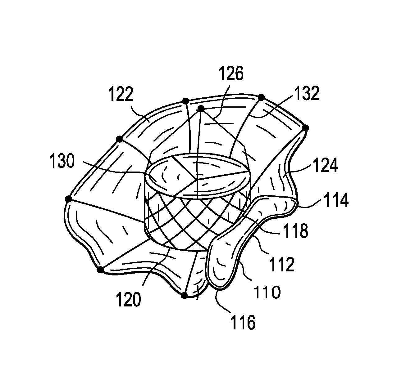
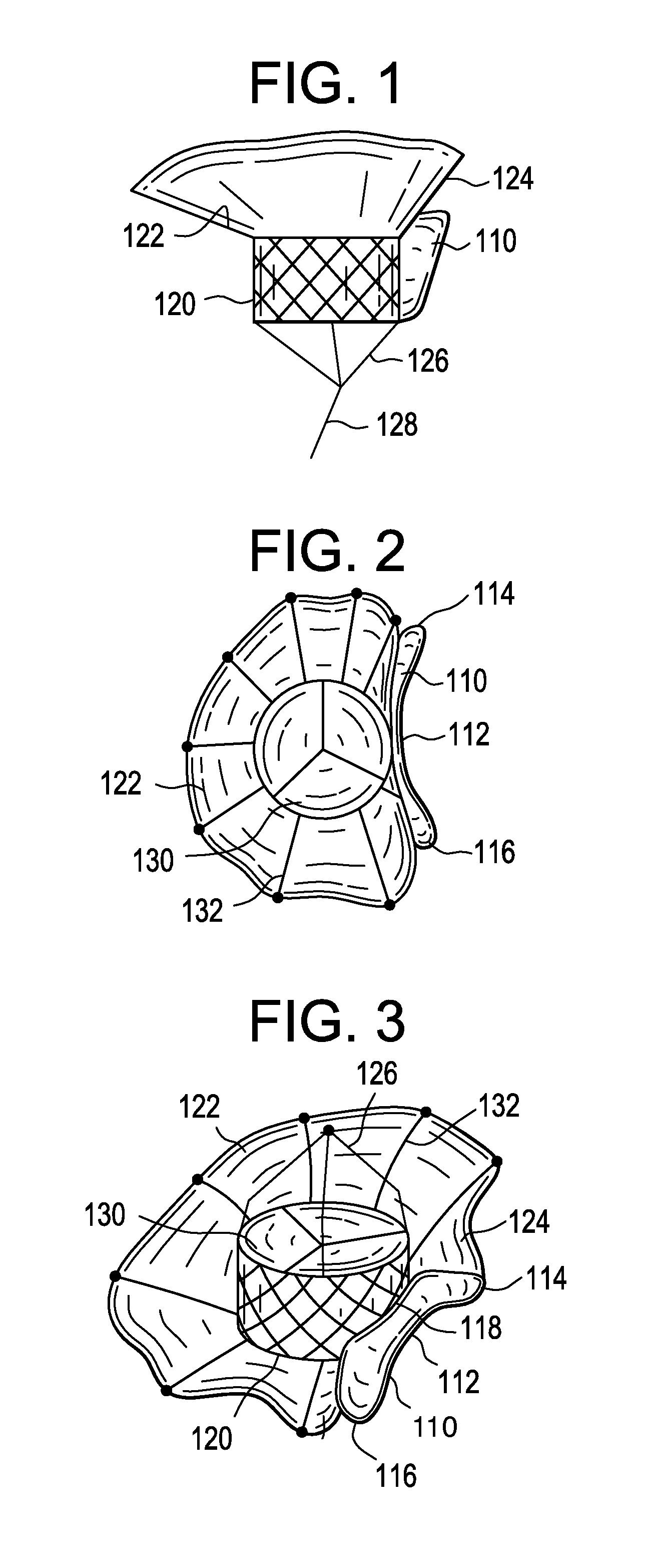
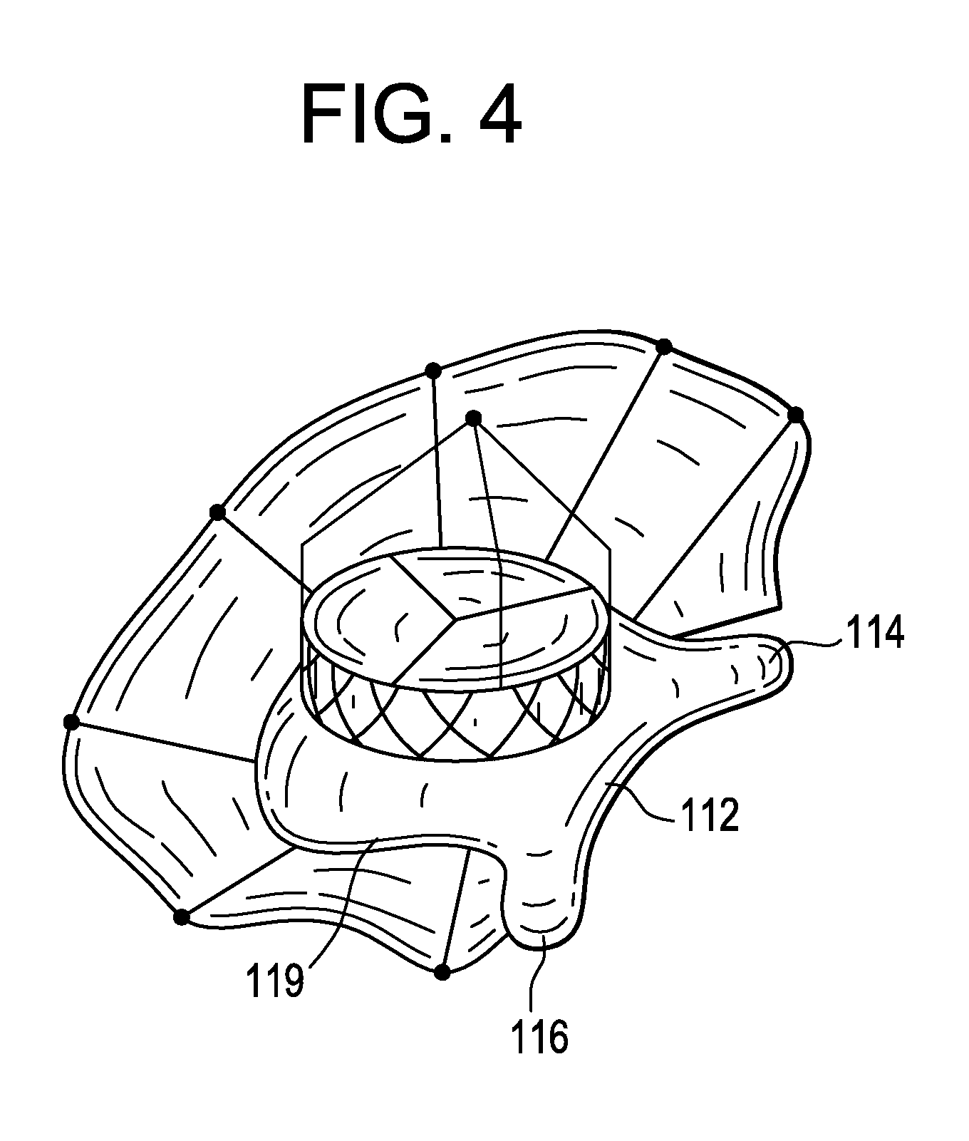
[0074]The inflatable annular sealing device, aka filled shell, functions by forming a filled shell or pouch of elastomeric silicone, stabilized tissue or synthetic material attached to the underside of the collar or cuff structure, wherein during systole the subvalvular space between the collar and native leaflet(s) are filled to form an additional seal against retrograde hemodynamic forces. During ventricular contraction or systole, the blood is ejected towards the prosthetic mitral valve. Retrograde blood hitting the prosthetic valve leaflets cause the leaflets to close, preventing regurgitation into the left atrium. Retrograde blood will then fill the subannular space around the chordae tendinae, which is frequently the cause and location of leakage around prosthetic valves which have been deployed into and through the native valve and annulus. However, the inflatable annular sealing device is constructed with a size and / or type o...


PUM


Abstract

This invention relates to a pre-configured compressible transcatheter prosthetic cardiovascular valve having an improved anterior leaflet sealing component comprising an inflatable annular sealing device made of a shell of elastomeric material, stabilized tissue or synthetic material, attached to the stent, and wherein during deployment of the valve the shell is filled to form a subvalvular seal. The invention also relates to methods for deploying such a valve for treatment of a patient in need thereof.

Description

CROSS REFERENCE TO RELATED APPLICATIONS[0001]This application claims priority to and the benefit of U.S. Provisional Patent Application No. 61 / 807,689, filed on Apr. 2, 2013, which is incorporated herein by reference in its entirety.STATEMENT REGARDING FEDERALLY SPONSORED RESEARCH OR DEVELOPMENT[0002]No federal government funds were used in researching or developing this invention.NAMES OF PARTIES TO A JOINT RESEARCH AGREEMENT[0003]Not applicable.SEQUENCE LISTING INCLUDED AND INCORPORATED BY REFERENCE HEREIN[0004]Not applicable.BACKGROUND[0005]1. Field of the Invention[0006]This invention relates to an improved transcatheter prosthetic heart valve that comprises an inflatable annular sealing device for reducing or preventing leaking around an implanted self-expanding stent and valve assembly that is anchored within the mitral valve or triscuspid valve of the heart using an optional integral cuff to anchor the valve and using one or more tethers anchored to the heart, and a delivery ...

Claims


Application Information

Patent Timeline
Patent Type & Authority Patents(United States)
IPC IPC(8): A61F2/07A61F2/24A61F2/06
CPCA61F2/07A61F2/2412A61F2/2418A61F2/2457A61F2/2487A61F2002/077A61F2250/0003
Inventor TEGELS, ZACHARY J.EKVALL, CRAIG A.VIDLUND, ROBERT M.
Owner TENDYNE HLDG
Why Eureka
Try Eureka