
Device and System for Transcatheter Mitral Valve Replacement

a technology device, which is applied in the field of transcatheter mitral valve replacement, can solve the problems of high morbidity, high risk of open heart surgery, and high mortality risk, and achieve the effect of preventing perivalvular leakag

Inactive Publication Date: 2011-12-29
AVALON MEDICAL +1
View PDF6 Cites 233 Cited by
  • Summary
  • Abstract
  • Description
  • Claims
  • Application Information

AI Technical Summary

Benefits of technology

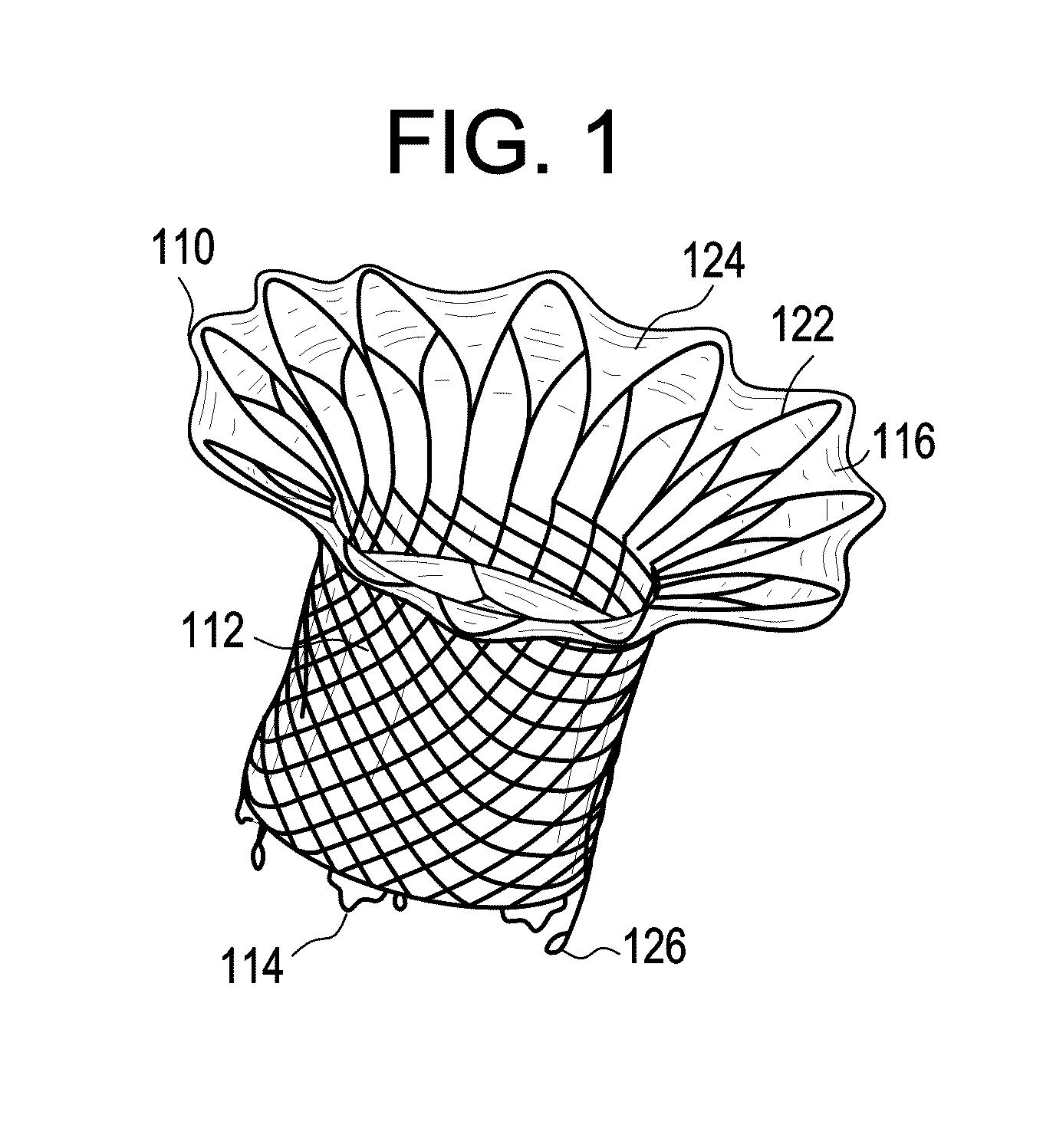
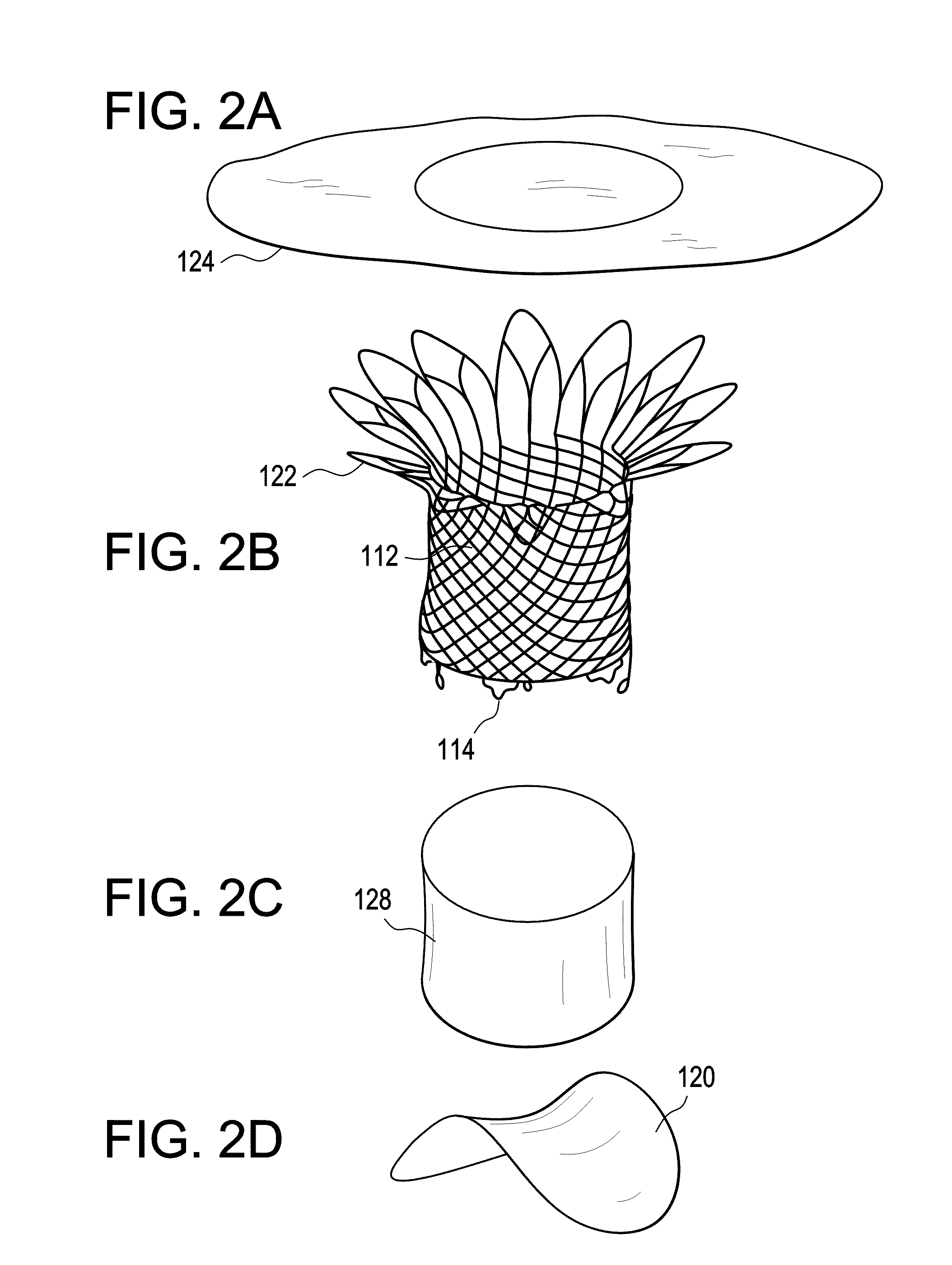
The present invention is about a compressible prosthetic heart valve replacement that can be deployed into a closed beating heart using a minimally invasive procedure. The valve is designed to be compressed and ejected from a delivery system, such as a catheter, and can be made from various materials and designs. The valve can be attached to the heart using tethers or other anchoring methods. The invention provides a prosthetic heart valve that can be easily deployed and can accommodate the movement of the heart throughout the cardiac cycle. The invention also includes various features such as a cuff that can be covered with tissue or synthetic polymer, the use of an expandable tubular stent with a cuff, the use of an expandable internal leaflet assembly, and the use of a feathered cuff design. The invention allows for the replacement of a damaged heart valve without the need for open heart surgery.

Problems solved by technology

Valvular heart disease and specifically aortic and mitral valve disease is a significant health issue in the US Annually approximately 90,000 valve replacements are conducted in the US.
While valve replacement surgery typically carries a 1-4% mortality risk in otherwise healthy persons, a significantly higher morbidity is associated to the procedure largely due to the necessity for extra-corporeal circulation.
Further, open heart surgery is often poorly tolerated in elderly patients.
This is in part reflective of the greater level of complexity associated to the native mitral valve apparatus and thus a greater level of difficulty with regards to inserting and anchoring the replacement prosthesis.

Method used


Image

  • Device and System for Transcatheter Mitral Valve Replacement
  • Device and System for Transcatheter Mitral Valve Replacement
  • Device and System for Transcatheter Mitral Valve Replacement

Examples


Embodiment Construction

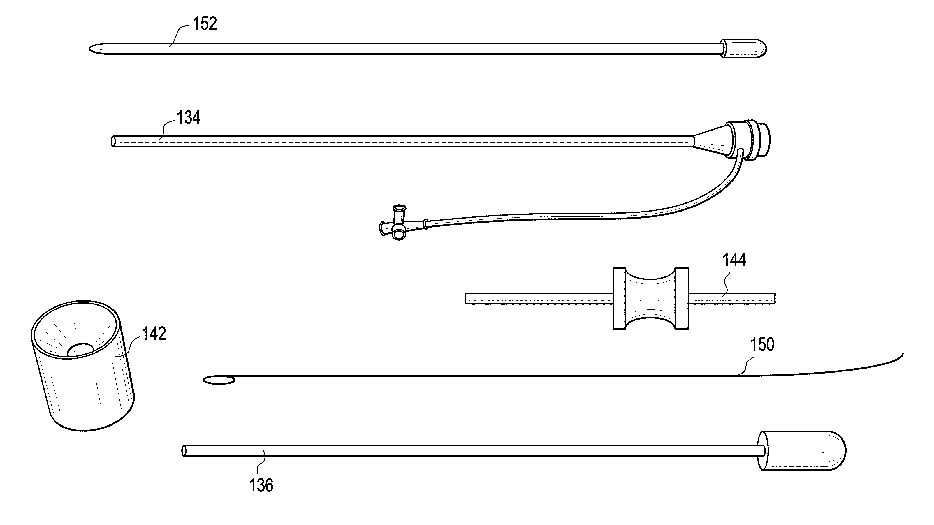
[0077]The present invention provides in one embodiment a prosthetic heart valve that comprises a self-expanding valve assembly that is anchored within the mitral valve of the heart using an integral cuff to anchor the valve and using one or more tethers anchored to the heart. It is contemplated as within the scope of the invention to provide a prosthetic heart valve having as an anchoring system both an integral cuff or collar and one or more tethers for tissue anchoring.

[0078]The prosthetic heart valve comprises a self-expanding tubular stent having a cuff at one end and tether loops for attaching tethers at the other end, and disposed within the tubular stent is a leaflet assembly that contains the valve leaflets, the valve leaflets being formed from stabilized tissue or other suitable biological or synthetic material. In one embodiment, the leaflet assembly comprises a wire form where a formed wire structure is used in conjunction with stabilized tissue to create a leaflet suppor...


PUM


Abstract

This invention relates to the design and function of a compressible valve replacement prosthesis which can be deployed into a beating heart without extracorporeal circulation using a transcatheter delivery system. The design as discussed focuses on the deployment of a device via a minimally invasive fashion and by way of example considers a minimally invasive surgical procedure preferably utilizing the intercostal or subxyphoid space for valve introduction. In order to accomplish this, the valve is formed in such a manner that it can be compressed to fit within a delivery system and secondarily ejected from the delivery system into the annulus of a target valve such as a mitral valve or tricuspid valve.

Description

CROSS REFERENCE TO RELATED APPLICATIONS[0001]This application claims priority to U.S. Provisional application Ser. No. 61 / 267,739, filed Dec. 8, 2009, which is incorporated herein by reference in its entirety.STATEMENT REGARDING FEDERALLY SPONSORED RESEARCH OR DEVELOPMENT[0002]No federal government funds were used in researching or developing this invention.NAMES OF PARTIES TO A JOINT RESEARCH AGREEMENT[0003]Not applicable.SEQUENCE LISTING INCLUDED AND INCORPORATED BY REFERENCE HEREIN[0004]Not applicable.BACKGROUND[0005]1. Field of the Invention[0006]This invention relates to a transcatheter mitral valve replacement and a delivery system therefor.BACKGROUND OF THE INVENTION[0007]The current state of knowledge is as follows.[0008]Valvular heart disease and specifically aortic and mitral valve disease is a significant health issue in the US Annually approximately 90,000 valve replacements are conducted in the US. Traditional valve replacement surgery, the orthotopic replacement of a h...

Claims


Application Information

Patent Timeline
Patent Type & Authority Applications(United States)
IPC IPC(8): A61F2/24
CPCA61F2/2418A61F2/2436A61F2/2457A61F2230/0078A61F2220/0016A61F2230/005A61F2230/0054A61F2002/9522A61F2210/0014A61F2220/0075A61F2310/00023A61F2250/0069A61F2250/0039A61F2250/0018A61F2/848A61F2/9522
Inventor SCHANKERELI, KEMALORTON, E. CHRISTOPHER
Owner AVALON MEDICAL
Learn More