Prosthetic valves and related inventions

a prosthetic valve and valve body technology, applied in the field of prosthetic valve improvements, can solve the problems of high morbidity, high cost, and high risk of open heart surgery in elderly patients, and achieve the effect of maintaining structural integrity and improving stability

Active Publication Date: 2016-11-01
TENDYNE HLDG
View PDF694 Cites 195 Cited by
  • Summary
  • Abstract
  • Description
  • Claims
  • Application Information

AI Technical Summary

Benefits of technology

[0143]In a preferred embodiment, the prosthetic mitral valve contains an improved stent body that has a low height to width profile and the leaflet structure disposed within the stent is positioned at or near the atrial end of the stent body.
[0148]In another preferred embodiment, the prosthetic heart valve has a tether which is used to position the valve cuff into the mitral annulus to prevent perivalvular leak.

Problems solved by technology

Valvular heart disease and specifically aortic and mitral valve disease is a significant health issue in the US.
While valve replacement surgery typically carries a 1-4% mortality risk in otherwise healthy persons, a significantly higher morbidity is associated to the procedure largely due to the necessity for extra-corporeal circulation.
Further, open heart surgery is often poorly tolerated in elderly patients.
This is in part reflective of the greater level of complexity associated to the native mitral valve apparatus and thus a greater level of difficulty with regards to inserting and anchoring the replacement prosthesis.
One problem involves the repetitive deformation of the nitinol wire material commonly used in the manufacture of stented valves.
Fatigue fractures of the metal wire material can result in a catastrophic structural failure whereby the valve support structure weakens and breaks.
Although failure of a single wire may not necessarily cause a structural collapse of the entire valve, over time, this possibility becomes a practical reality.
When the consequence of valve failure means the death of the patient, the importance cannot be overstated.
Various problems continue to exist in this field, including problems with perivalvular leaking around installed prosthetic valve, lack of a good fit and stability for the prosthetic valve within the native mitral annulus, atrial tissue erosion, excess wear on the metallic structures, interference with the aorta at the posterior side of the mitral annulus, difficulties in deployment and retrieval, and lack of customization, to name a few.

Method used


Image

  • Prosthetic valves and related inventions
  • Prosthetic valves and related inventions
  • Prosthetic valves and related inventions

Examples


Embodiment Construction

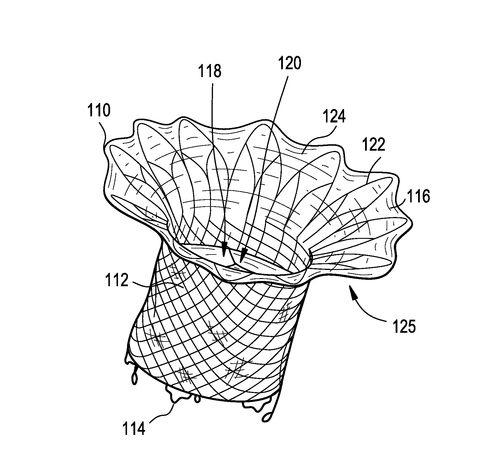
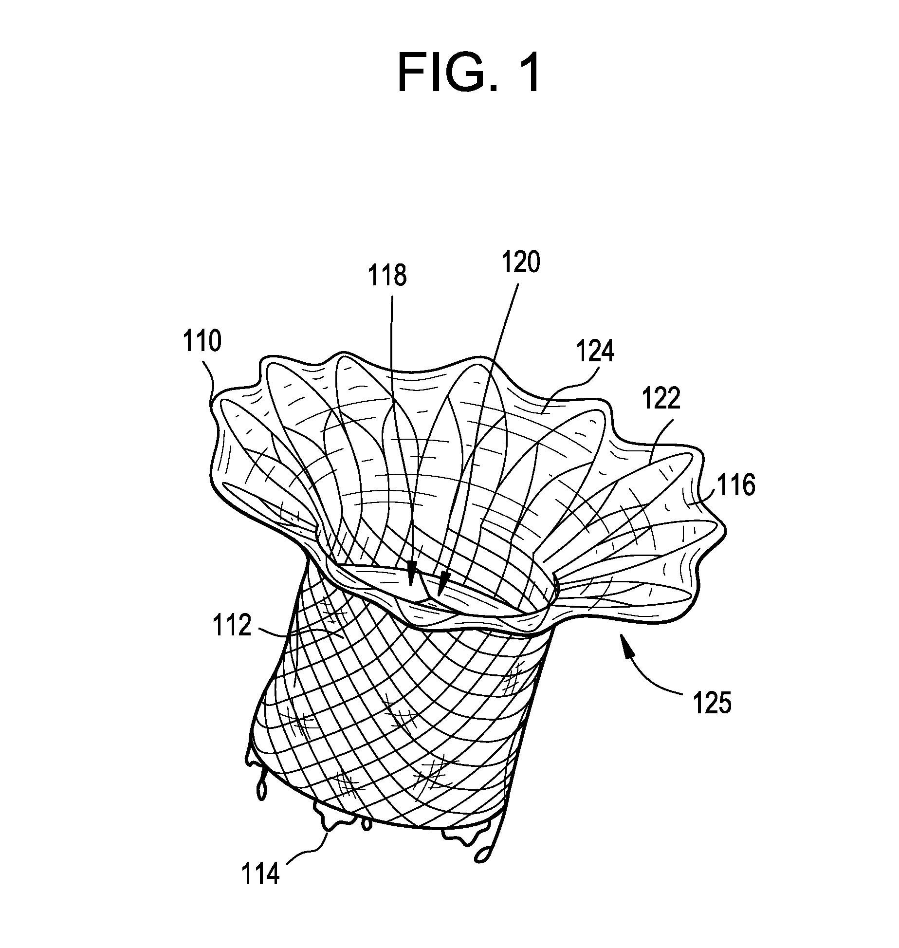
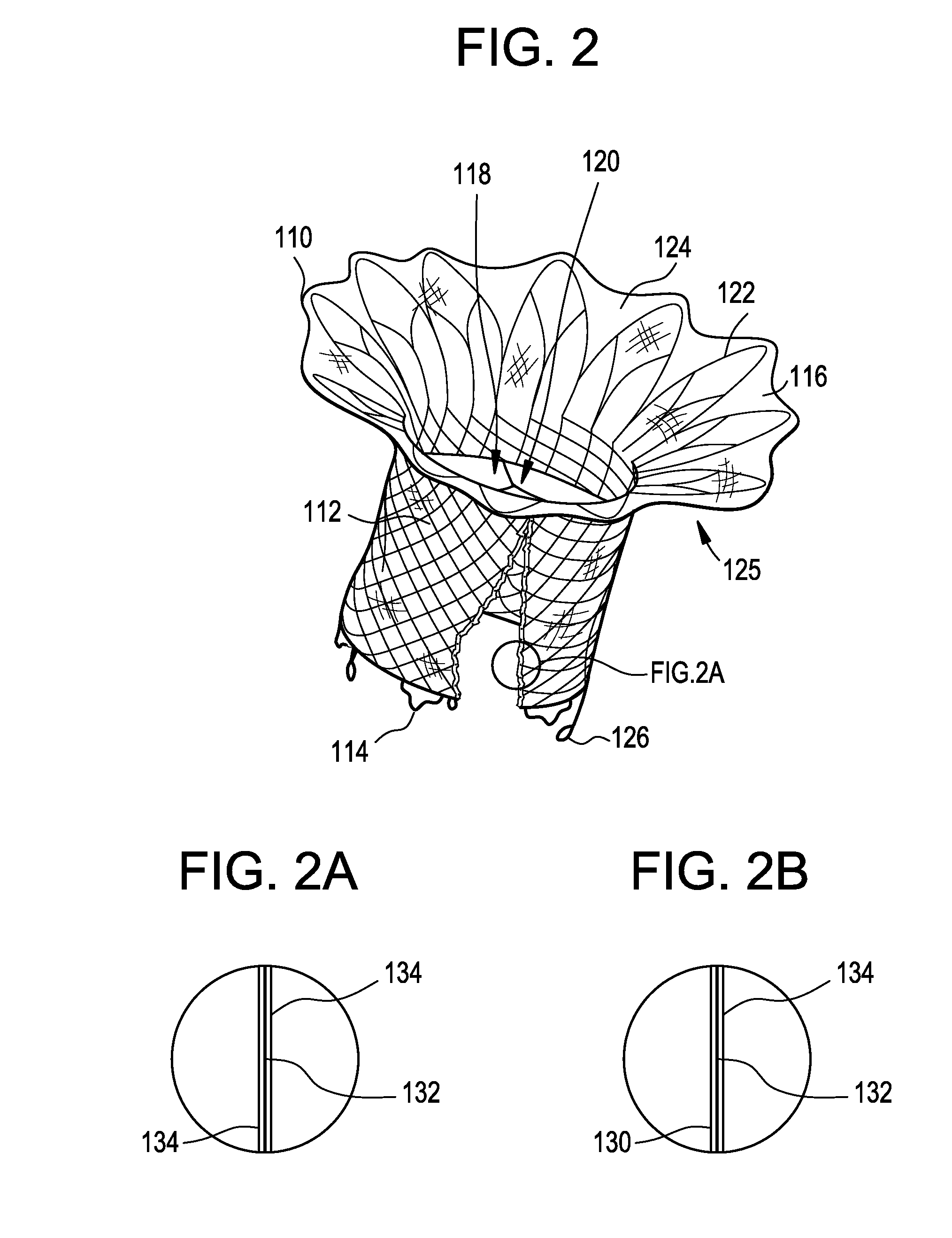
[0274]The present invention provides various improvements in the design and components of prosthetic valves, especially for use in cardiac surgeries. Specifically, the invention relates to improved designs and features providing better stability, fit, durability and ease of delivery and retrieval for such prosthetic valves. For the purposes of this application, the terms “collar” and “sealing cuff” are used interchangeably.

Improved Surface Components

[0275]In one embodiment, the invention provides improvement in the surface components and structures for prosthetic valves intended to be deployed into a closed beating heart using a transcatheter delivery system. The combination of unique features herein addresses many of the issues and points of failure in current valve technology and provides a highly developed approach to the extraordinary number of problems that arise when attempting to provide a medical device of this type. The invention provides improved in-growth of the prostheti...


PUM

PropertyMeasurementUnit
angleaaaaaaaaaa
anglesaaaaaaaaaa
lengthaaaaaaaaaa

Abstract

This invention relates to the design and function of a compressible valve replacement prosthesis, collared or uncollared, which can be deployed into a beating heart without extracorporeal circulation using a transcatheter delivery system. The design as discussed focuses on the deployment of a device via a minimally invasive fashion and by way of example considers a minimally invasive surgical procedure preferably utilizing the intercostal or subxyphoid space for valve introduction. In order to accomplish this, the valve is formed in such a manner that it can be compressed to fit within a delivery system and secondarily ejected from the delivery system into the annulus of a target valve such as a mitral valve or tricuspid valve.

Description

CROSS REFERENCE TO RELATED APPLICATIONS[0001]This application claims priority under 35 U.S.C. §371 to, and is a U.S. national phase application of, International Application No. PCT / US2012 / 050579, filed Aug. 13, 2012, which claims priority to and the benefit of U.S. Provisional Application Ser. No. 61 / 522,542, filed Aug. 11, 2011; U.S. Provisional Application Ser. No. 61 / 522,468, filed Aug. 11, 2011; U.S. Provisional Application Ser. No. 61 / 522,450, filed Aug. 11, 2011; U.S. Provisional Application Ser. No. 61 / 522,476, filed Aug. 11, 2011; U.S. Provisional Application Ser. No. 61 / 523,134, filed Aug. 12, 2011; U.S. Provisional Application Ser. No. 61 / 564,462, filed Nov. 29, 2011; and U.S. Provisional Application Ser. No. 61 / 615,264, filed Mar. 24, 2012, the disclosures of which are incorporated herein by reference in their entireties.STATEMENT REGARDING FEDERALLY SPONSORED RESEARCH OR DEVELOPMENT[0002]No federal government funds were used in researching or developing this invention.N...

Claims


Application Information

Patent Timeline
Patent Type & Authority Patents(United States)
IPC IPC(8): A61F2/24A61L27/34A61L33/00A61L27/36A61B17/064A61B17/04
CPCA61F2/2412A61F2/2418A61L27/34A61L27/3625A61L27/3629A61L33/0011C08L67/04A61B17/0401A61B17/064A61B17/0644A61B2017/0404A61F2/2436A61F2/2457A61F2220/005A61F2220/0008A61F2220/0058A61F2220/0091A61F2230/005A61F2230/0013A61F2230/0034A61F2230/0054A61F2230/0067A61F2230/0091A61L2400/16A61L2430/20A61F2210/0004A61F2210/0014A61F2310/00023A61F2310/00077A61F2/2409A61F2/2427
Inventor VIDLUND, ROBERTSCHANKERELI, KEMALLOZONSCHI, LUCIANLUTTER, GEORG
Owner TENDYNE HLDG
Why Eureka
Try Eureka