
Method and practical use system for measuring the imbalance power in electrical installations, and the device for calibration thereof

a technology of imbalance power and electrical equipment, which is applied in the direction of electric devices, instruments, transportation and packaging, etc., can solve the problems of inability to meet the application of the effect measurement, and the calibrators of the measurement instruments for the imbalance power formed by passive elements are not known in industrial practi

Active Publication Date: 2012-09-18
UNIV POLITECNICA DE VALENCIA
View PDF2 Cites 1 Cited by
  • Summary
  • Abstract
  • Description
  • Claims
  • Application Information

AI Technical Summary

Benefits of technology

"The invention provides a method and system for measuring the imbalance power of an electrical system or facility. This is done by measuring the voltage and current of each phase of the system and analyzing them to determine the total imbalance power. The invention solves the problem of previous methods that only measured the imbalance power at the overall level of the system, rather than at the individual component parts. The invention uses a complex number to represent the imbalance power, making it easier to measure the total power of the system. The technical effect of the invention is to provide a more accurate and complete measure of the imbalance power in an electrical system or facility."

Problems solved by technology

This greatly limits and hinders its application for the measurement of the effects of imbalances in industrial practice.
Moreover, calibrators of measurement instruments for the imbalance power formed by passive elements are not known in industrial practice.

Method used


Image

  • Method and practical use system for measuring the imbalance power in electrical installations, and the device for calibration thereof
  • Method and practical use system for measuring the imbalance power in electrical installations, and the device for calibration thereof
  • Method and practical use system for measuring the imbalance power in electrical installations, and the device for calibration thereof

Examples


Embodiment Construction

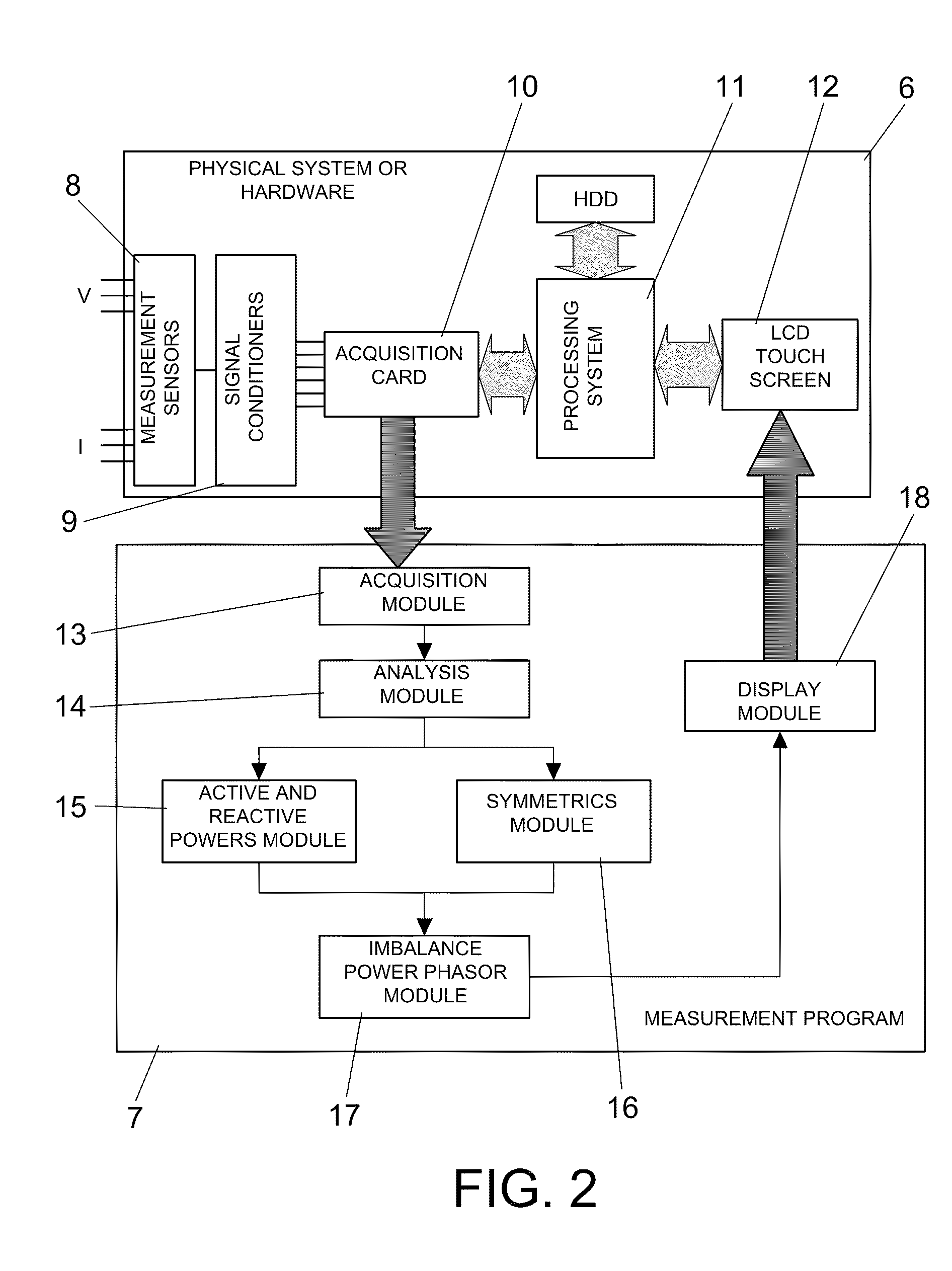
[0005]The invention relates to a method and to a system for the measurement of the imbalance power of an electrical facility and device for its calibration.

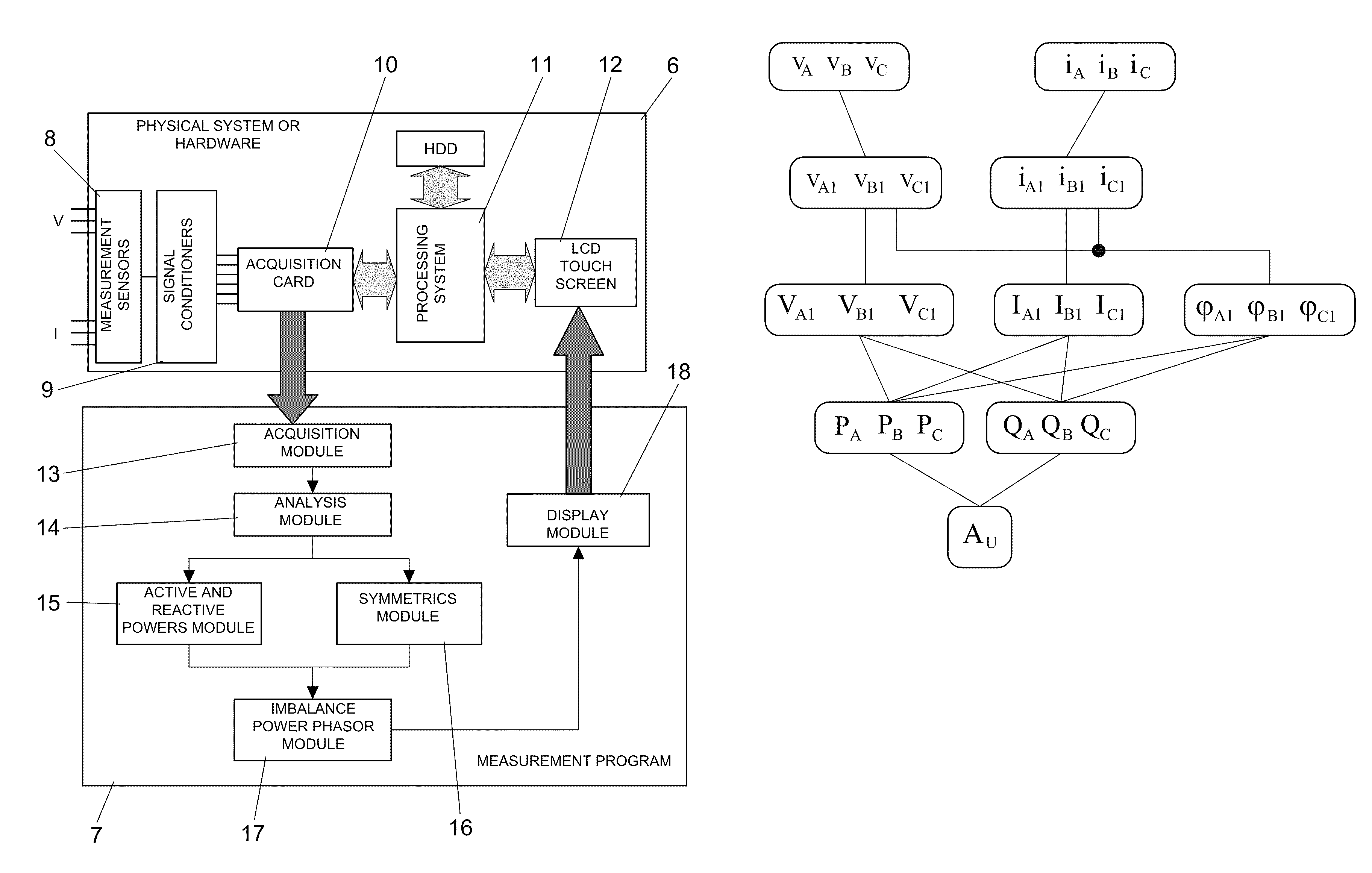
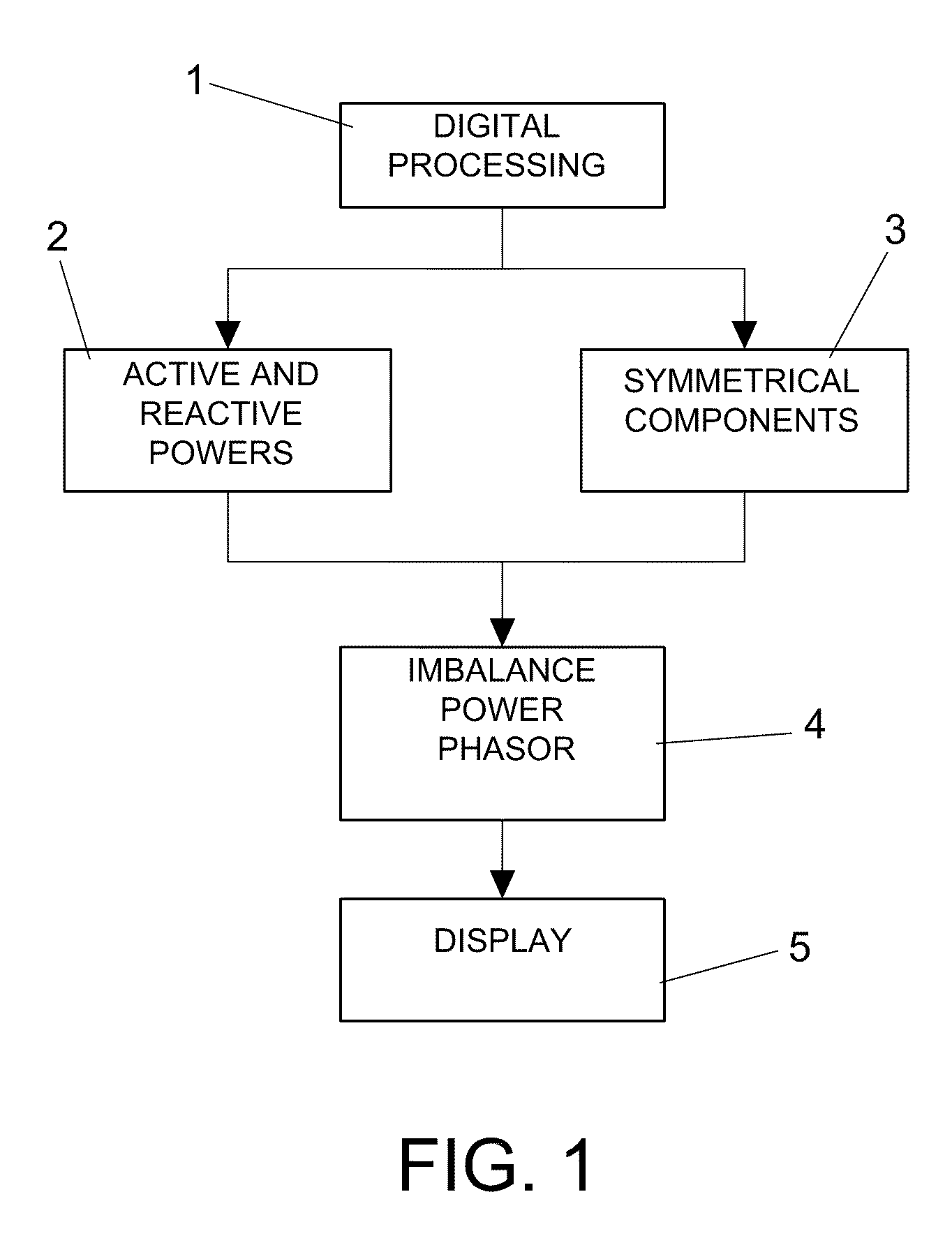
[0006]To achieve this, the concept of “imbalance power phasor” is established as a fundamental contribution, this being a magnitude whose modulus is the imbalance power and whose argument indicates the phase or phases in which the imbalance is greatest, along with whether the resistive or reactive loads have a greater impact on the imbalance. One of the properties, among others, of this new magnitude, which is a complex number rather than real, is that the imbalance power phasor of an electrical system or facility is equal to the sum of the imbalance power phasors of each of the parts of the electrical system or facility, which considerably simplifies the obtaining of the value of the total imbalance power of the system.

[0007]This “imbalance power phasor” magnitude is not currently known in the technical literature and therefore ...


PUM


Abstract

Method and practical use system for measuring the imbalance potential of an electrical installation or system comprising:i) acquiring instantaneous values of voltage (vA, vB, vC) and electrical intensity (iA, iB, iC) of each of the phases A, B, C of the installation, and breaking them down into their fundamental frequency components (vA1, vB1, vC1), (iA1, iB1, iC1);ii) obtaining effective voltage and intensity values and angles for initial phase difference between voltage and intensity, and, starting from these effective values obtaining active powers (PA, PB, PC) and reactive (QA, QB, QC) potentials for each of the phases;iii) from the active and reactive potentials, obtaining (4) a phasor imbalance potentials (ĀU) according to the following expression:ĀU=√{square root over (2)}( <o ostyle="single">p< / o>·|PA+a2PB+aPC|+ <o ostyle="single">q< / o>·|QA+a2QB+aQC|)where a=1|120° and p and q are orthogonal unit phasors.The invention also relates to a device for calibrating (21) instruments for measurement instruments of this imbalance power.

Description

OBJECT OF THE INVENTION[0001]The present invention relates in general to the measurement and calibration of measurement instruments for the phenomenon of imbalance in electrical facilities, and more particularly to three-phase electrical systems with three and four wires.BACKGROUND OF THE INVENTION[0002]Imbalance power is a concept that is known in the technical literature, and is a magnitude which quantifies the effects of the phenomenon of imbalance in electrical facilities. Different formulations have been developed for this imbalance power—taking into account different theories established on electrical power—which only give its magnitude, a real number. The imbalance power is not conservative, in other words, it does not obey the Principle of Conservation of Energy, and therefore the imbalance power of an electrical facility is not equal to the sum of the imbalance powers corresponding to each of its component elements. This greatly limits and hinders its application for the me...

Claims


Application Information

Patent Timeline
Patent Type & Authority Patents(United States)
IPC IPC(8): G01R21/00
CPCG01R29/16G01R35/007G01R21/00G01R21/06
Inventor CAZORLA, NAVARRO ANTONIOGINER, GARCIA JOSELEON, MARTINEZ VICENTEMONTANANA, ROMEU JOAQUIN
Owner UNIV POLITECNICA DE VALENCIA
Learn More